
Subscribe to Our Youtube Channel
Related Manuals for Frico SL-DC1


Summary of Contents for Frico SL-DC1
- Page 1 Original instructions Installations and user manual SL/SLS-DC1 SL/SLS-R1 ..83 ..2 ..52 ..27...
- Page 2 Conformity This unit complies with European directives: • Electro-magnetic compatibility 2004/108/CE. • Low tension directive 2006/95/CE Symbols The pictograms in the next chapter provide the necessary unmistakable way information for correct, safe use of the machine in a rapid, Safety pictograms Generic danger Danger due to heat Signals to the personnel that the operation described could...
-
Page 3: Table Of Contents
General General warnings Fundamental safety rules Product range Nominal technical features Overall dimensions Installation of SL/SLS - DC1/R1 Positioning the unit Installation modes Minimum installation distances Side opening Vertical floor or wall installation Horizontal or ceiling installation (SL) Mounting front grill safety support (SL) Dimensions Condensation discharge Filling the system... -
Page 4: General
After unpacking, make sure that all the components are present. owner or user or transferred onto another system. If not, contact the Frico agent who sold the appliance to you. All repair or maintenance interventions must be performed Frico appliances must be installed by an authorised installer... -
Page 5: Product Range
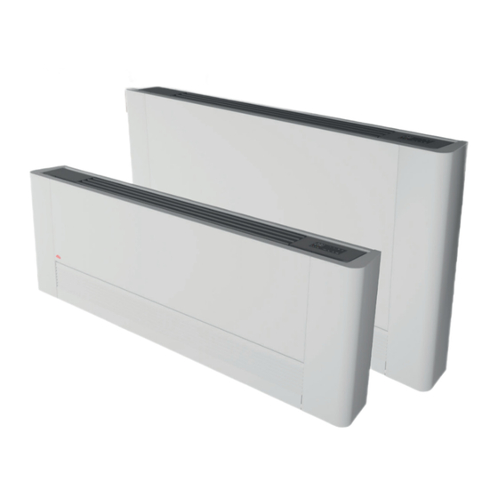
Product range The water batteries is offered in 2 sizes with different performances and dimensions. 1. SL Fan convector SL-DC is suitable for wall mounting. Fan convector SL-R1 is suitable for wall and ceiling mounting. 2. SLS Fan convector SLS-DC is suitable for wall mounting. Fan convector SLS-R1 is suitable for wall and ceiling mounting for heating operation. -
Page 6: Overall Dimensions
Overall dimensions 2 pipes U.M. SL/SLS 200 SL/SLS 400 SL/SLS 600 SL/SLS 800 SL/SLS 1000 Dimensions 1135 1335 1535... -
Page 7: Installation Of Sl/Sls - Dc1/R1
The operations for the mounting of machines with fixtures on the invalidate the warranty and hence Frico shall not respond for any damage to persons, animals or property. right are exactly the same. -
Page 8: Side Opening
Side opening On the left-hand side lift the cover that protects the screw, On the opposite side, lift the cover that protects the screw and loosen the screw that fixes the left panel, then move it slightly unscrew it. to the left and lift it up. Move the side panel slightly to the right and lift it out. -
Page 9: Horizontal Or Ceiling Installation (Sl)
Horizontal or ceiling installation (SL) Using the paper template, trace on the ceiling the position of the position is prohibited. . two fixing brackets and the two rear screws. Using a suitable drill, make the holes and insert the toggle bolts (2 for each bracket); Carefully check the inclination of the exhaust pipe. -
Page 10: Dimensions
Dimensions U.M. 1000 Minium inner pipeline diameter The choice and sizing of the hydraulic lines must be made by an The hydraulic lines and joints must be thermally insulated. expert who must operate according to the rules of good technique and the laws in force, taking into account that undersized pipes Avoid partially insulating the pipes. -
Page 11: Filling The System
Mounting the condensation discharge pipe in the horizontal version (SL-R1 cooling) check that the "L" pipe and the flexible rubber hose are N.B. for the horizontal installation carefully note the following correctly connected to the bowl. precautions: slide in the side of the machine keeping the pipe in position up make sure that the machine is installed perfectly level or with against the front grill. -
Page 12: Electrical Connections
III. Before doing any work, make sure the power is switched off. Mounting of valve kits The convector must be mounted with Frico valve kits for SL/SLS see separate manuals. For SL, valve kit V20687, art nr. 76648... -
Page 13: Installation Of Internal Control (Eca644) Model Dc1
Installation of internal control (ECA644) model DC1 Mounting, setting and connection of on-board machine control panels ECA644 The controls have two independent free contacts to on the battery manages the minimum in heating (30°C) control a chiller and a boiler and a presence input. The and maximum in cooling (20°C) functions. -
Page 14: Setting Auxiliary Functions Dip-Switches B And C
Setting auxiliary functions dip-switches B and C There are two dip-switches on the electronic control cooling, the continuous ventilation at the minimum panel for setting the functions of the appliance as speed, even after the set point has been reached required. -
Page 15: Mounting Air Temperature Probe
Mounting air temperature probe To position the temperature probe (ref. A): fix the probe in the special hook (ref. D). pass the probe through the hole on the shoulder (ref. B) insert the probe in the lower hole (ref. C) -
Page 16: Wiring Diagram
Wiring diagram water temperature probe 10 kΩ boiler go-ahead output (free contact max 1A) cold water temperature probe 10 kΩ (only ECA chiller go-ahead output (free contact max 1A) 647) air temperature probe 10 kΩ presence sensor input (if closed, the fan coil goes fan motor DC inverter into stand-by.) RS water probe (2kΩ) (only for ECA644 versions) -
Page 17: Installation Of Control For Remote Operation (B10642) Model R1
Installation of control for remote operation (B10642) model R1 Mounting and connecting the fan control for remote adjustment B10642 Mounted on board it can control the motor; with modular Consider this impedance value for the control outputs to speed; the motor regulation can be done through a 0-10 B10642, especially if you want to control several units in V DC analogue input with 25 kΩ... -
Page 18: Diagram For B10642 Connections With 0-10 V Dc Thermostats/Signals
Diagram for B10642 connections with 0-10 V DC thermostats/signals Make the electrical connections to a thermostat that is suitable for the purpose, according to the diagram in the picture 230V-50 Hz electric power supply RS version wiring device pilot input 0÷10 V RS water probe (2kΩ) hot water solenoid valve (230V/50Hz 1A powered fan motor DC inverter... -
Page 19: Troubleshooting
Troubleshooting Troubleshooting The ventilation does not activate even if there is hot or cold In case of water leaks or anomalous functioning immediately cut water in the hydraulic circuit. off the power supply and close the water taps. The appliance leaks water during the heating function. The appliance leaks water only during the cooling function. -
Page 20: User Instructions
User instructions SMART TOUCH electronic panel with continuous on- board modulation This control makes the room temperature adjustment completely autonomous (with adjustable offset via keyboard) through AUTO, After 20 seconds from the last action the panel brightness will SILENT, NIGHT and MAX pictograms by means of a probe located be reduced to increase the comfort during night use and on in the lower side of the device ensuring anti-freeze safety even the display will appear the room temperature. -
Page 21: General Start-Up
General start-up In order to control the device from the control panel, it first has to - Start the system by toggling the main switch be connected to mains. If the power line is provided with a main - Switch on the system with the main switch. switch, it should be on. -
Page 22: Automatic Operation
Automatic operation Operation Display Hold the AUTO key. The function activation will be signalled by the relative symbol on the display The ventilation speed will be adjusted automatically between a algorithm. minimum and a maximum value, based on the actual distance between the room temperature and the setpoint using a PI Silent operation Operation... -
Page 23: Deactivation
Deactivation Operation Display Press the ON stand-by for about 2 s: When the device is in "stand-by" status (no function) there are no light signals on the display. The control ensures anti-freeze safety even when set to stand-by. Room temperature probe offset adjustment In some cases the detected values might not represent the real deviations from the room temperature using a reliable tool! temperature due to the fact that the temperature probe is located... -
Page 24: Maintenance
Maintenance Routine maintenance is indispensable to keep the cooler- and annually for others, by the Technical Service Assistance, convector in perfect working condition, safe and reliable over the technically authorised and prepared, using always original spare years. This can be done every six months for some interventions parts. - Page 25 Extraction of filter cells in the versions with mobile aspiration panel Insert your hands under the end of mobile panel Lift and extract the mobile panel Press the plastic lug Extract the filter flap filter Plastic tabs extraction filter Cleaning filtering seats suck up the powder with a vacuum cleaner It is forbidden to use the unit without the net filters.
-
Page 26: Energy Saving Tips
Ending Cleaning Operations For the versions with a grill with flaps, insert the two lugs into upper part. the special slots, turn it and hook it up with a slight tap on the slots tabs For the versions with a mobile panel, rest it in its position, parallel to the front panel and press until it is blocked. - Page 27 SL/SLS- Quickguide 2 x adaptor - included in box Ø12 Ø22 230V Adaptor G 3/4" 10 cm Type B [mm] C [mm] D [mm] E [mm] F [mm] G [mm] H [mm] I [mm] J [mm] K [mm] A [mm] SLS200 75,7 88,2...
- Page 28 Water connection Type L [mm] SL200 SL400 SL600 1135 SL800 1335 SL1000 1535 Type L [mm] SLS200 SLS400 SLS600 1135 SLS800 1335 SLS1000 1535 ...
- Page 29 Main offi ce Frico AB Tel: +46 31 336 86 00 Industrivägen 41 SE-433 61 Sävedalen mailbox@frico.se Sweden www.frico.net For latest updated information and information about your local contact: www.frico.net...
Need help?
Do you have a question about the SL-DC1 and is the answer not in the manual?
Questions and answers