
Related Manuals for Frico SWL Series


Summary of Contents for Frico SWL Series
- Page 1 Original instructions ... 16 ... 24 ... 28 ... 20 ... 32 ... 36 ... 52 ... 40 ... 44 ... 48 ... 56...
- Page 2 Introduktionssidorna består huvudsakligen av bilder. För översättning av de engelska texter som används, se respektive språksidor. The introduction pages consist mainly of pictures. For translation of the English texts used, see the respective language pages. Introduksjonssidene består hovedsakelig av bilder. For oversettelse av de engelske tekstene, se de respektive språksidene Les pages de présentation contiennent principalement des images.
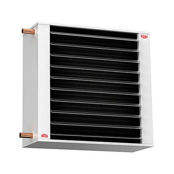
- Page 3 Fan heater SWL Fan heater SWL 2. Mounting brackets SWB 3. Basic filter SWSFT 4. Filter section, deep-pleated bagfilter EU3 SWF 5. Return air intake SWD 6. Extra air director SWLR Accessories SWLR SWSFT SWB0 Mounting brackets SWL02 SWEF1 Extra filter cassette EU3 SWL12 SWB1 Mounting brackets SWL12 SWEF2...
- Page 4 Dimensions Inlet Outlet ø Ø [mm] [mm] [mm] [mm] [mm] [mm] [mm] [mm] [mm] [mm] [mm] [mm] SWL02 SWL12 SWL22 SWL32/33 Mounting brackets SWB Filter section SWF ø20 42,3 [mm] [mm] [mm] [mm] SWB0 [mm] [mm] [mm] [mm] [mm] SWB1 SWF1 SWB2 SWF2...
-
Page 5: Electrical Installation
Controls TKS16 KRT1900 CB20 RE1,5/RE3/RE7 KRTV19 Type Description HxWxD [mm] Electronic thermostat with knob and 1-pole main switch 80x80x31 TKS16 KRT1900 Capillary tube thermostat 165x57x60 KRTV19 Capillary tube thermostat with knob 165x57x60 CB20 2-step change-over switch for air flow, max 10A 155x87x43 RE1,5 5-step change-over switch for air flow, max. - Page 6 Wiring diagrams Internal wiring diagram SWL02 SWL12 SWL22 SWL32 SWL33 SWL02-22 SWL32-33 Lo Hi 230V Lo Hi 230V Control by thermostat only SWL02-33 SWL02-33 230V SD20 KRT/V SD20 230V TVVS20/25 KRT/V KRT1900/KRTV19 SWL02-33 SWL02-33 230V SD20 TKS16 SD20 230V TVVS20/25 TKS16 >t C TKS16...
- Page 7 Wiring diagrams Thermostat and 2-step control The thermostat controls only heat SWL02-33 SWL02-33 230V SD20 CB20 SD20 KRT/V 230V TVVS20/25 KRT/V KRT1900/KRTV19 1/2 o CB20 CB20 SWL02-33 SWL02-33 230V SD20 CB20 SD20 TKS16 230V TVVS20/25 TKS16 >t C TKS16 CB20 1/2 o CB20...
- Page 8 Wiring diagrams Thermostat and 2-step control The thermostat controls heat and fan SWL02-33 SWL02-33 230V SD20 CB20 SD20 KRT/V 230V TVVS20/25 KRT1900/KRTV19 KRT/V 1/2 o CB20 CB20 SWL02-33 SWL02-33 230V SD20 CB20 SD20 TKS16 230V TVVS20/25 TKS16 TKS16 >t C CB20 1/2 o CB20...
- Page 9 Wiring diagrams Thermostat and 5-step control The thermostat controls only heat SWL02-33 SWL02-33 230V SD20 SD20 RE 1,5-7 KRT/V TVVS20/25 230V KRT/V KRT1900/KRTV19 RE 1,5-7 RE1,5-7 SWL02-33 SWL02-33 230V SD20 SD20 RE 1,5-7 TKS16 TVVS20/25 230V TKS16 >t C TKS16 RE 1,5-7 RE1,5-7...
- Page 10 Wiring diagrams Thermostat and 5-step control The thermostat controls heat and fan SWL02-33 SWL02-33 230V SD20 SD20 RE 1,5-7 KRT/V TVVS20/25 230V KRT/V KRT1900/KRTV19 RE 1,5-7 RE1,5-7 SWL02-33 SWL02-33 230V TKS16 SD20 SD20 RE 1,5-7 TVVS20/25 230V TKS16 >t C TKS16 RE 1,5-7 RE1,5-7...
-
Page 11: Technical Specifications
Technical specifications Fan heater SWL (IP44) Type Heat output* Air flow Air flow Sound power* Sound pressure* [kW] [m³/h] [m³/s] [dB(A)] [dB(A)] SWL02 30/43 650/1120 0,18/0,31 SWL12 41/54 1450/2450 0,40/0,68 SWL22 46/59 2200/3950 0,61/1,10 SWL32 46/56 4230/6450 1,18/1,79 SWL33 47/53 3700/5850 1,02/1,63 Fan heater SWL (IP44) - Page 12 Output charts water...
- Page 13 Output charts water...
- Page 14 Output charts water...
- Page 15 Output charts water...
- Page 16 Installation and operating instructions General Instructions air distribution. By turning the fan heater, Read these instructions carefully before pipe connections are possible on both sides. installation and use. Keep this manual for future reference. Mounting without accessories The product may only be used as set out in Measure and mark the drilling holes on the the assembly and operating instructions.
-
Page 17: Maintenance
fittings. For correct inlet and outlet are not cleaned properly, vibrations/noise can connection of the heating coil, see dimension occur and severly damage the bearings. If the sketch. vibration/noise remains after cleaning, please Note! Be careful while connecting the pipes to contact a certified technician. - Page 18 Handling of product at end of working life This product may contain substances necessary for functionality of product but potentially dangerous for the environment. The product should not be disposed mixed with general household waste but delivered to a designated collection point for environmental recycling.
- Page 19 Translation for introduction pages 1) Fan heater SWL 2) Mounting brackets SWB 3) Basic filter SWSFT 4) Filter section SWF 5) Return air intake SWD 6) Extra air director SWLR Technical specifications Heat output* [kW] Heat output Airflow* /h], [m Airflow Sound level* [dB(A)]...
- Page 21 Main offi ce Frico AB Tel: +46 31 336 86 00 Box 102 SE-433 22 Partille mailbox@frico.se Sweden www.frico.se For latest updated information and information about your local contact: www.frico.se...
Need help?
Do you have a question about the SWL Series and is the answer not in the manual?
Questions and answers