Table of Contents
Advertisement
Quick Links
Advertisement
Table of Contents

Subscribe to Our Youtube Channel
Related Manuals for Frico SIReFAEMX


Summary of Contents for Frico SIReFAEMX
- Page 1 Original instructions SIRe Advanced Fan Heater Electric With quick guide SIReFAX SIReFAEMX ..62 ..22 ..42 ..2 ..82 ..102 ..122 ..142 ..162 ..182 For wiring diagram, please see last pages...
-
Page 2: Connect The System
SIRe Advanced Fan Heater Electric Quick guide/start up Enter ID/Operation without control unit The control system can control one or more Check that all constituent parts are present units in parallel (max 9). Each unit must get (see section Constituent parts). a unique ID number (1-9) which is set in the ID selector of the PC board. -
Page 3: Start Up
SIRe Advanced Fan Heater Electric Start up Start up System supplied with power. At the first start up, the start-up wizard is run and the basic Select mixing cabinet On in the start-up settings are made. Fan and heating steps wizard. -
Page 4: Table Of Contents
Enter ID/Operation without control unit Start up Unit with mixing cabinet Start up Constituent parts SIReFAX (without mixing cabinet) SIReFAEMX (with mixing cabinet) Option Operating modes Operating modes (without mixing cabinet) Operating modes (with mixing cabinet) Control unit SIReUA1 Overview... -
Page 5: Constituent Parts
SIRe Advanced Fan Heater Electric Constituent parts SIReFAX (without mixing cabinet) SIReUA1, Wall unit cover SIReB1X, External SIReIT02, internal control unit PC board Basic temperature sensor Competent and Advanced SIReCC, SIReOTX, SIReA1X, modular cable outdoor temperature PC board HUB sensor Advanced Dimensions constituent parts Type... -
Page 6: Sirefaemx (With Mixing Cabinet)
SIRe Advanced Fan Heater Electric SIReFAEMX (with mixing cabinet) SIReUA1, Wall unit cover SIReB1X, External SIReIT02, internal control unit PC board Basic temperature sensor 2 m Competent and Advanced PSM01, damper SIReOTX, SIReCC, SIReA1X, motor outdoor modular cable PC board HUB... -
Page 7: Option
SIRe Advanced Fan Heater Electric Option SIReRTX, external SIReUR, kit SIReCJ6, joint SIReCJ4, joint SIReCC, room temperature for recessed piece piece modular cable sensor installation Type RSK-no. E-no. Description HxWxD SIReRTX 673 09 22 87 510 12 External room temperature sensor 70x33x23 SIReUR* 673 09 21... -
Page 8: Operating Modes
SIRe Advanced Fan Heater Electric Operating modes Operating modes (with mixing cabinet) The control is based on two operating modes: Operating modes (without mixing cabinet) Control is based on the three operating Thermostat / Manual fan modes: Manual • Thermostat / Manual fan Thermostat / Manual fan •... -
Page 9: Control Unit Sireua1
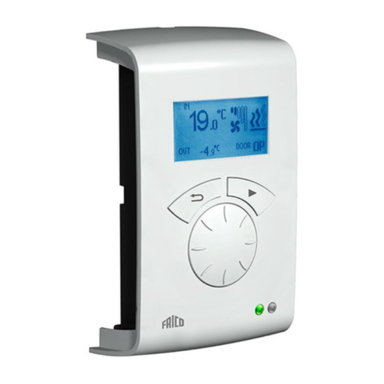
SIRe Advanced Fan Heater Electric Control unit SIReUA1 Overview 19 .0 -5.0 Statuswindow °C °C Fan speed step Back arrow Forward arrow Heating step Rotary dial Meny Week program Week program Night Alarm Red led Week program Run signal Green led Out of operation Explanations Statuswindow... -
Page 10: Main Menu
SIRe Advanced Fan Heater Electric Main menu System on/off Current settings Switch the whole unit off manually. In Off the Displays set room temp, high speed limit and display goes out; as soon as a button is pushed week program status. the display lights and shows System on/off. -
Page 11: Installer Status Screen
SIRe Advanced Fan Heater Electric Installer menu To check which days a certain program is active, select a week day by pressing the To enter the Installer menu, code 1932 is forward arrow, the program is marked and entered. Select the digits using the rotary dial those days that the program is used will be and confirm using the forward arrow. -
Page 12: Fan Settings
SIRe Advanced Fan Heater Electric Heating settings Week program is activated by selecting On, under Week program on/off. In On-mode, Make settings for heating. a sun, moon or Off in the Status window appears to indicate day, night respectively >Installer menu Off-function. - Page 13 SIRe Advanced Fan Heater Electric Factory setting Temperature control without mixing Heating step limit: 2 (SE06-15, 20) 3 (SE30) cabinet (fan mode Thermostat /Automatic fan): Comfort Sensor calibration 1. Fan starts at set setpoint value. If the sensor displays the wrong values these 2.
-
Page 14: External Filter Guard
SIRe Advanced Fan Heater Electric Filter guard settings Last filter change To check the number of run time hours since Filter alarm alarms when the set fixed run the last filter replacement, select Last filter time has been exceeded. change. The time is reset when the filter >Installer menu alarm is reset. -
Page 15: External Control (Bms)
SIRe Advanced Fan Heater Electric Night damper pos. External control (BMS) Desired current damper position nighttime. BMS functions can be activated under External control. >Installer menu>Mixing cabinet >Installer menu>Mixing cabinet Activate External on/off (5-30V AC/DC from Min outlet temp. Night damper pos. BMS) or 0-10V fan control by selecting On Day damper pos. - Page 16 SIRe Advanced Fan Heater Electric Diagram: Fan step at incoming 0-10V DC voltage level, 4 step Diagram: Fan step at incoming 0-10V DC voltage level, 2 step Diagram: Heating step for incoming 0-10V DC voltage level, 3-step. Diagram: Heating step for incoming 0-10V DC voltage level, 2-step.
-
Page 17: General Settings
User reset (Room temp. day resp. night, high speed limit) to factory setting. Service menu >Installer menu>General settings >Installer menu>User reset The service menu is password protected and Execute user reset? is used for support in contact with Frico or Function test authorised installer. User reset... -
Page 18: Alarm And Error Codes
Frico. Power failure Note that in case of power failure the time settings need to be checked, if the time is not set correctly week program will be affected. - Page 19 SIRe Advanced Fan Heater Electric Table - Alarm Alarm Cause Action Motor alarm Thermal switch has deployed. Check that nothing is obstructing the unit’s air One or several motors have intake and exhaust. When the overheated motor overheated. (Only units with has cooled the thermal switch shuts again and withdrawn thermal switches.) the alarm can be reset.
- Page 20 Internal sensor Fault on or missing Check connection of the sensor. If there is faults internal sensor in the no sensor, contact Frico for support. unit. ID Error Two or more SIReB1X Contact Frico for support. in the system have different programs.
- Page 21 SIRe Advanced Fan Heater Electric Connecting external control - including BMS functions SIReA1X RPM indication Heating indication Outdoor temp. sensor External night reduction External alarm IN Ext. speed ctrl. 0-10V DC IN Ext. Heating control 0-10V DC IN External ON/OFF ALARM OUT (BMS) Operation indication OUT (BMS) RPM indication...
- Page 22 SIRe Advanced Fan Heater Electric Connections between SIReB1X and Panther SE06, SE09, SE12 and SE15. SIReB1X SE06-15...
- Page 23 SIRe Advanced Fan Heater Electric Connections between SIReB1X and Panther SE20 SIReB1X SE20...
- Page 24 SIRe Advanced Fan Heater Electric Connections between SIReB1X and Panther SE30 SIReB1X SE30...
- Page 25 SIRe Advanced Fan Heater Electric Wiring diagram - Advanced – without mixing cabinet BMS INDICATION OUT (potential free contact max 3A, 230V) ALARM OUT (BMS) (potential free contact, max 3A, 230V) EXTERNAL ON/OFF, 5-30V AC/DC EXTERNAL HEAT 0-10V DC IN EXTERNAL RPM 0-10V DC IN EXTERNAL ALARM IN (potential free contact)
- Page 26 SIRe Advanced Fan Heater Electric Wiring diagram - Advanced – with mixing cabinet INDICATION OUT (BMS) (potential free contact, max 3A, 230V) ALARM OUT (BMS) (potential free contact, max 3A, 230V) EXTERNAL ON/OFF 5-30V AC/DC EXTERNAL HEAT 0-10V DC IN EXTERNAL RPM 0-10V DC IN EXTERNAL ALARM IN (potential free contact)
- Page 27 SIRe Advanced Fan Heater Electric Wiring diagram - Advanced – parallel connection BMS INDICATION OUT (potential free contact max 3A, 230V) ALARM OUT (BMS) (potential free contact, max 3A, 230V) EXTERNAL ON/OFF, 5-30V AC/DC EXTERNAL HEAT 0-10V DC IN EXTERNAL RPM 0-10V DC IN EXTERNAL ALARM IN (potential free contact) EXTERNAL SETBACK TEMP.
- Page 28 Main offi ce Frico AB Tel: +46 31 336 86 00 Box 102 Fax: +46 31 26 28 25 SE-433 22 Partille mailbox@frico.se Sweden www.frico.se For latest updated information and information about your local contact: www.frico.se...
Need help?
Do you have a question about the SIReFAEMX and is the answer not in the manual?
Questions and answers