Table of Contents
Advertisement
Quick Links
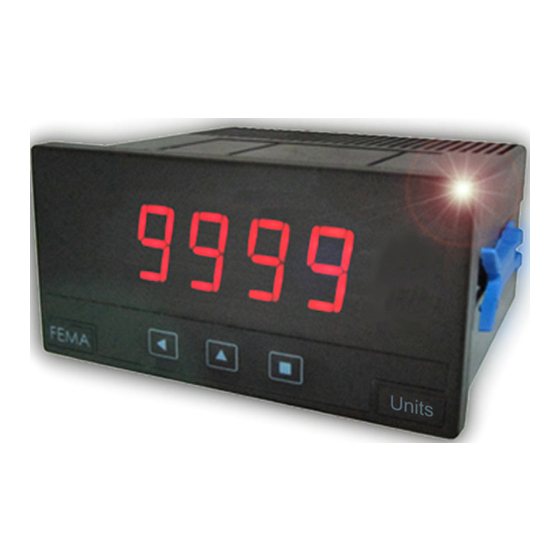
Series M . M40-D
DC Voltmeter and DC Ammeter
PANEL MEtErS
DC voltmeter and DC ammeter for panel mount. Scalable reading. Measure up to 600 Vdc and up to
5 Adc. Standard 96 x 48 mm size (1/8 DIN). Reading with 4 digit display. Fast access to alarm setpoints,
'on power up' function, 'measure' function, configurable reading brightness. Universal AC and DC
power. Up to 3 optional modules for output and control (relays, analog outputs, Modbus RTU com-
munications, RS-485 ASCII, RS-232, ...)
2149r07
ELECTRONICS
FOR
PANEL METERS . SIGNAL CONVERTERS . LARGE DISPLAYS
Tel. (+34) 93.729.6004 info@fema.es
User's Manual
INDUSTRIAL
AUTOMATION
www.fema.es
Advertisement
Table of Contents

Related Manuals for Fema Electronica M40-D


Summary of Contents for Fema Electronica M40-D
- Page 1 ELECTRONICS INDUSTRIAL AUTOMATION PANEL METERS . SIGNAL CONVERTERS . LARGE DISPLAYS Series M . M40-D DC Voltmeter and DC Ammeter PANEL MEtErS DC voltmeter and DC ammeter for panel mount. Scalable reading. Measure up to 600 Vdc and up to 5 Adc.
-
Page 2: Table Of Contents
Index 1. Panel meter M40-D..... . . 2 1.12 Full configuration menu ....12 1.1 How to order . -
Page 3: Front View
FEMA ELECTRÓNICA . Series M . M40-D 1.2 Front view 1.5 Signal connections - DC voltage Alarms To configure the voltage DC measure, select the jumper for the de- sired scale as indicated in the table below. Then activate the selected scale in the configuration menu (see section 1.11.1) and connect the... -
Page 4: Technical Specifications
FEMA ELECTRÓNICA . Series M . M40-D 1.7 Technical specifications Mechanical Digits mounting panel number of digits connections plug-in screw terminal 7 segments led housing material ABS, polycarbonate (V0) color red or green weight <150 grams digit height 14 mm... -
Page 5: Mechanical Dimensions (Mm)
FEMA ELECTRÓNICA . Series M . M40-D 1.7 Technical specifications (cont.) Functions included Section ‘Fast access’ 1.11.5 ‘On Power Up’ 1.11.7 ‘Field correction’ yes, high and low signals 1.11.2 Alarms double setpoints 1.11.3 activation delays deactivation delays hysteresis inverted relays... -
Page 6: How To Operate The Menus
FEMA ELECTRÓNICA . Series M . M40-D 1.9 How to operate the menus the instrument has two menus accessible to the user : Example of operation inside the ‘configuration menu’. ‘Configuration menu’ (key SQ) (<) 1. The SQ (<) key enters into the ‘Fast access’... -
Page 7: Configuration Menu
FEMA ELECTRÓNICA . Series M . M40-D 1.11 Configuration menu 1.11.1 Initial set-up Press ‘SQ’ (<) for 1 second to access the ‘configuration menu’. For a description on how to operate inside the menus see section . For a full vision of the ‘configuration menu’ structure see To configure the initial set up of the instrument, select the measure 1.12... -
Page 8: Alarms
FEMA ELECTRÓNICA . Series M . M40-D 1.11 Configuration menu (cont.) 1.11.3 Alarms The ‘Alarms’ (‘ALr’) menu configures the independent activation of Alarms up to 3 relay outputs, installed with the R1 optional modules (see section 2.1). For outputs up to 4 and 6 relays, see special modules R2, R4 and R6 at section 2.6. -
Page 9: Display Filters
FEMA ELECTRÓNICA . Series M . M40-D 1.11 Configuration menu (cont.) 1.11.4 Display filters The instrument provides several functions to personalize the reading Display Fixed digits Fix digits of the display values • the ‘Fixed Digits’ (‘FIX.d’) allows to fix each digit to a fixed value. -
Page 10: Fast Access
FEMA ELECTRÓNICA . Series M . M40-D 1.11 Configuration menu (cont.) 1.11.5 Fast access Tools The ‘UP’ (5) key at the front of the instrument gives access to a list of functions configurable by the operator. See section 1.9 for an ex- planation on how to operate the ‘fast access’... -
Page 11: Menu 'Key Le
FEMA ELECTRÓNICA . Series M . M40-D 1.11 Configuration menu (cont.) 1.11.8 Menu ‘Key LE’ The ‘LE’ (3) key at the front of the instrument can be configured to Key LE No function activate several functions. Only one function can be assigned to the ‘LE’... -
Page 12: Full Configuration Menu
FEMA ELECTRÓNICA . Series M . M40-D 1.12 Full configuration menu Press ‘SQ’ (<) for 1 second to access the ‘Configuration 1.11 menu’. See section for a description of each menu entry. Deactivation delay Scale ±600 Vdc Input Setpoint 2 Scale ±100 Vdc... - Page 13 FEMA ELECTRÓNICA . Series M . M40-D 1.12 Full configuration menu (cont.) Configuration menu for the module installed at Opt.1 Tools Option 1 Configuration menu for the module installed at Opt.2 Key UP Setpoint 1 Option 2 (‘fast access’) Configuration menu for the module installed at Opt.3...
-
Page 14: To Access The Instrument
FEMA ELECTRÓNICA . Series M . M40-D 1.13 To access the instrument You may need to access the inside of the instrument to add or re- place internal modules. Use a flat screwdriver to unlock the upper clips marked with ‘A’. Then unlock the lower clips marked with ‘B’ and remove the front cover. -
Page 15: Precautions On Installation
FEMA ELECTRÓNICA . Series M . M40-D 1.15 Precautions on installation soon as power is connected. The instrument does not have protection fuse, Risk of electrical shock. Instrument terminals can be connected the fuse must be added during installation. to dangerous voltage. -
Page 16: Output And Control Modules
FEMA ELECTRÓNICA . Series M . M40-D 2. Output and control modules 2.1 Module R1 2.2 Module AO The R1 module provides 1 relay output to M Series panel meters. the AO module provides 1 analog output with 4/20 mA or 0/10 Vdc Up to a maximum of 3 R1 modules can be installed in a single instru- configurable output range. -
Page 17: Module Rtu
FEMA ELECTRÓNICA . Series M . M40-D 2.3 Module RTU 2.4 Module S4 The RTU module provides a Modbus RTU communications module The S4 module provides a RS-485 communications module for M for M Series of panel meters. The RTU module implements function Series of panel meters. -
Page 18: Module S2
FEMA ELECTRÓNICA . Series M . M40-D 2.5 Module S2 2.6 Modules R2, R4, R6 The S2 module provides a RS-232 communications module for M The R2, R4 and R6 modules provide 2, 4 and 6 relay outputs for M Series of panel meters. - Page 19 FEMA ELECTRÓNICA . Series M . M40-D...
-
Page 20: Other Options
FEMA ELECTRÓNICA . Series M . M40-D 3. Other options 3.1 Option NBT 3.3 Option G Instruments without front key- Green led digits option. pad. To configure the instrument, remove the meter from the panel and remove the front filter. Inter- nal press buttons for configuration are accessible. -
Page 21: Accessories
FEMA ELECTRÓNICA . Series M . M40-D 4. Accessories 4.1 THM benchtop housing 4.3 Adapter DRA-M Benchtop housing for M Series Adapter for DIN rail mount, for panel meters. Handle with three M Series panel meters. selectable positions. Power con- nector with manual switch and fuse holder. - Page 22 FEMA ELECTRÓNICA . Series M . M40-D Notes...
- Page 23 FEMA ELECTRÓNICA . Series M . M40-D Notes...
- Page 24 Panel meters Panel meters Signal converters Standard 96 x 48 mm Miniature 48 x 24 mm Panel meters Large format meters Bar meters Compact 72 x 36 mm ‘Customized’ Isolators Low cost instruments MODBUS truerMS truerMS rS-485 Load FEMA ELECTRÓNICA, S.A. Altimira 14 - Pol.
Need help?
Do you have a question about the M40-D and is the answer not in the manual?
Questions and answers