
Subscribe to Our Youtube Channel
Related Manuals for Smithco 30-000-B


Summary of Contents for Smithco 30-000-B
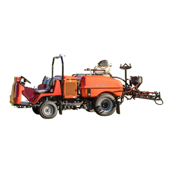
- Page 1 Parts & Service Spray Star 3180 Model 30-000-B SN: 300G159 August 2013 Product Support: Hwy SS & Poplar Ave; Cameron WI 54822 1-800-891-9435 productsupport@smithco.com...
-
Page 2: Table Of Contents
CONTENTS Introduction ..........1-3 Accessories ........52-108 Introduction ................ 1 Plumbing 3182 System ......54-55 (Raven 440) General Safe Practices............2 Plumbing 3184 System ......56-57 (Raven 203) Specifications ..............3 Plumbing 3185/3186 ..58-59 (Envizio Pro II/SharpShooter) Optional Spray Equipment..........3 Plumbing 3187/3188 60-63 (Raven 440/SharpShooter) .... -
Page 3: Introduction
INTRODUCTION Smithco Thank you for purchasing a product. Read this manual and all other manuals pertaining to the Spray Star 3180 carefully as they have safety, op- erating, assembly and maintenance instructions. Failure to do so could result in personal injury or equipment damage. - Page 4 17. Stop engine before making repairs/adjustments or checking/adding oil to the crankcase. 18. Use parts and materials supplied by Smithco only. Do not modify any function or part. 19. Use caution when booms are down as they extend out beyond the center line of the machine.
-
Page 5: Specifications
SPECIFICATIONS SPRAY STAR 3180 WEIGHTS AND DIMENSIONS Length 128" (325 cm) Width 72" (183 cm) Height w/ ROPS 84" (213 cm) Height w/ Booms Folded 136" (345 cm) Wheel Base 68" (173 cm) Weight Empty 2340 lbs (1061 kg) Weight Full 4950 lbs (2245 kg) SOUND LEVEL (DBA) At ear level... -
Page 6: Maintenance
MAINTENANCE Before servicing or making adjustments to machine, stop engine and remove key from igni- tion. Use all procedures and parts prescribed by the manufacturer's. Read the engine manual before operation. LUBRICATION Use No. 2 General purpose lithium base grease and lubricate every 100 hours. The Spray Star 3180 has 7 grease fittings. - Page 7 MAINTENANCE ENGINE OIL With strict emission control regulations now in effect, the CF-4 and CG-4 engine oils have been developed for use with low sulfur fuels, for On-Highway vehicle engines. When Non-Road engines run on high sulfur fuel, it is advisable to use a "CF or better" classification engine oil with Total Base Number (a minimum TBN of 10 is recommended).
-
Page 8: Wheel Creep
MAINTENANCE BATTERY Batteries normally produce explosive gases which can cause personal injury. Do not allow flames, sparks or any ignited object to come near the battery. When charging or working near battery, always shield your eyes and always provide proper ventilation. Battery cable should be disconnected before using “Fast Charge”. -
Page 9: Adjustments
ADJUSTMENTS SPRAY PUMP WITH BELT Located to the right of the engine. The belt should have approximately " (13mm) of deflection in the center of the top strand. SAFETY INTERLOCK SWITCH To adjust the interlock switch on the back hydrostatic pump loosen the set screw on the front half of the switch, with the ignition switch OFF. -
Page 10: Service Chart
SERVICE CHART Before servicing or making adjustments to the machine, stop engine, block wheels and remove key from ignition. Follow all procedures and ONLY use parts prescribed by the manufacturer. Read the engine manual before maintenance. The suggested maintenance checklist is not offered as a replacement for the manufacturer’s engine manual but as a supplement. -
Page 11: End User's Service Chart
END USER SERVICE CHART Duplicate this page for routine use... -
Page 12: Storage
STORAGE To prevent damage from freezing, pour window washer fluid into spray systems tank and operate pump to circulate mix through gun and hose back to tank. Open boom control to circulate through rest of spray system. 1. Clean the exterior surfaces of the engine. 2. - Page 13 NOTES...
-
Page 14: Wiring Diagram
WIRING DIAGRAM REF# PART# DESCRIPTION QUANTITY 77-223 Timer 30-042-06 Relay 50-359 Warning Light 10-556 Speedometer 12-017 Hour Meter 14-292 Seat Switch 13-488 Ignition Switch 32-014 Lights 15-725 Mount Panel End 15-727 Switch Actuator 15-782 Rocker Switch, Unlit 15-729 Mount Panel Middle 15-726 Switch Body, Light 15-732... - Page 15 WIRING DIAGRAM REF# PART# DESCRIPTION QUANTITY 77-207 Buzzer 16-998 Hypro Pump 18-372 3-Way ball Valve 33-480 Pressure Switch 33-271 Buss Bar 33-272 Fuse, 15 AMP 33-273 Fuse, 30 AMP 33-509 Cruise Foot Switch 30-107 Wire Harness Battery ground to Fuse 33-084 Magnetic Coil 48-147...
-
Page 16: Hydraulic Diagram
HYDRAULIC DIAGRAM Use dielectric grease on all electrical connections. Letter Code Chart Center Inside Outside Bottom... - Page 17 HYDRAULIC DIAGRAM PARTS LIST REF# PART# DESCRIPTION QUANTITY 30-156 Hydraulic Hose 30-091 Hydraulic Hose 15-301 Orbitrol 30-094 Hydraulic Hose 15-839 Hydraulic Cylinder 14-531 Seal Kit 18-171 Seal Loc Adapter 30-025 Oil Tank 13-747 Filler Breather 13-586-03 Neck 8833-9 Suction Hose 18-222 Hose Clamp 8833-17...
- Page 18 BODY & FRAME DRAWING...
- Page 19 BODY & FRAME PARTS LIST REF# PART# DESCRIPTION QUANTITY 30-095 318 Gallon Tank (fiberglass) 25-372 Decal, Smithco 4" Star 30-016 Decal, Spray Star 3180 16-557 Square cap 17-615 Boom Carrier HB-12-13-150 Bolt - 13 x 1 HNFL-12-13 Flange Lock Nut...
- Page 20 NOSE CONE DRAWING...
-
Page 21: Parts
NOSE CONE PARTS LIST REF# PART# DESCRIPTION QUANTITY 13-726 Center Cap 27-077 Decal, Smithco Round 13-718 15" Steering Wheel 76-364 Square Boot 76-362 Mini Tilt steering HB-516-18-125 Bolt - 18 x 1 HNFL-516-18 Flange Whiz Lock Nut 48-187 Stub shaft... - Page 22 NOSE CONE DRAWING...
- Page 23 NOSE CONE PARTS LIST REF# PART# DESCRIPTION QUANTITY 48-066 Pedal Grip 10-163 Forward Foot Pedal HB-14-20-075 Bolt -20 x HNFL-14-20 Flange Whiz Lock Nut - 20 31-049 Button Plate 33-509 Master Control Switch HSTP-14-20-075 Machine Screw -20 x 7-867 SAE # 6 Adapter 15-301 Orbitrol 13-488...
- Page 24 LINKAGE DRAWING...
-
Page 25: Linkage
LINKAGE PARTS LIST REF# PART# DESCRIPTION QUANTITY 60-106 Control Lever 34-021 Linkage Rod HN-516-24 - 24 30-153 Center Console 42-766 Throttle Bracket 30-027 Relay Plate HSTP-516-18-075 Phillips Machine Screw -18 x HNFL-516-18 Flange Whiz Lock Nut 10-163 Forward Foot Pedal 48-066 Pedal Grip 15-015... - Page 26 FRONT AXLE DRAWING...
-
Page 27: Front Axle
FRONT AXLE PARTS LIST REF# PART# DESCRIPTION QUANTITY HP-18-150 Cotter Pin HNJ-58-18 Jam Nut - 18 30-071 Hub Assembly HNAR-100-14 Slotted Jam Nut 1 - 14 30-070 Left Spindle 50-081 Rubber Insulator 30-039 Front Axle 18-153 Bushing (part of 30-039) 14-344 Axle Pin HB-516-18-125... - Page 28 OIL AND FUEL TANK DRAWING...
- Page 29 OIL AND FUEL TANK PARTS LIST REF# PART# DESCRIPTION QUANTITY 13-747 Filler Breather 13-586-03 Fuel Tank Neck HSM-10-32-063 Machine Screw #10-32 x HWL-10 Lock Washer #10 30-025 Oil Tank 18-069 Pipe Plug 18-433 Strainer 60-213 Strainer 18-397 90° Hose Barb Fitting 18-398 90°...
- Page 30 SEAT PANEL DRAWING...
-
Page 31: Seat Panel
SEAT PANEL PARTS LIST REF# PART# DESCRIPTION QUANTITY 31-046 Engine Cover (fiberglass) 31-048 T-Handle Latch 27-055 Flush Hinge HSM 10-32-100 Machine Screw #10-32-100 HNFL-10-32 Flange Whiz Lock Nut # 10 - 32 31-063 Roll Bar 31-058 Rod Pivot 50-081 Rubber Bumper HNFL-38-16 Flange Whiz Lock Nut 31-059... -
Page 32: Engine And Pumps
ENGINE AND PUMPS DRAWING... - Page 33 ENGINE, AND PUMPS PARTS LIST REF# PART# DESCRIPTION QUANTITY 30-042 Kubota Diesel Engine 33.5 HP 23-145 O-Ring HW-14 Flat Washer, 30-033 Throttle Cable Mount HBM-10-1.5-20 Metric Bolt, #10 - 1.5 x 20 HWLM-10 #10 Lock Washer 42-004-02 Air Cleaner Cap 30-040 Engine Mount LH HBM-10-1.5-30...
- Page 34 ENGINE AND PUMPS DRAWING...
- Page 35 ENGINE, AND PUMPS PARTS LIST REF# PART# DESCRIPTION QUANTITY 30-041 Engine Mount RH HBM-10-1.5-30 Bolt #10 - 1.5 x 30 HWLM-10 #10 Lock Washer 31-042 Muffler Support 50-111 Muffler Clamp 30-207 Pump Mount 16-161 Hose Barb Fitting 16-825 Hex Bushing 33-480 Pressure Switch 16-998...
-
Page 36: Cooler And Exhaust
COOLER AND EXHAUST DRAWING... - Page 37 COOLER AND EXHAUST PARTS LIST REF# PART# DESCRIPTION QUANTITY 30-133 Muffler HBFL-516-18-075 Flange Bolt - 18 x HNFL-516-18 Flange Lock Nut - 18 30-131 Muffler Hanger 30-052 Tank Carrier HB-38-16-300 Bolt - 16 x 3 HW-38 Washer HNFL-38-16 Flange Lock Nut - 16 30-050 Front Tank Mount...
-
Page 38: Rear Wheel Drive
REAR WHEEL DRIVE DRAWING... - Page 39 REAR WHEEL DRIVE PARTS LIST REF# PART# DESCRIPTION QUANTITY 18-394 Elbow 18-301 Straight Thread Elbow 30-099 Auburn Wheel Drive 30-100 Micro Spring Hydraulic Brakes 30-101 Eaton 2000 Series Hydraulic Motor 30-101-11 Seal Kit 17-615 Boom Tube 17-614 Boom Spacer HB-516-18-100 Bolt - 18 x 1 HW-516-18...
- Page 40 TANK DRAWING...
-
Page 41: Hypro Pump
TANK PARTS LIST REF# PART# DESCRIPTION QUANTITY HB-38-16-200 Bolt - 16 X 2 HW-38 Washer HNTL-38-16 Lock Nut - 16 30-051 Rear Tank Mount 8828-16 Foam Tape HB-38-16-300 Bolt - 16 x 3 HW-38 Washer HNFL-38-16 Flange Lock Nut - 16 30-095 318 Gallon Tank (fiberglass) 16-945... - Page 42 TURBO-QUAD AGITATOR DRAWING...
- Page 43 TURBO-QUAD AGITATOR PARTS LIST REF# PART# DESCRIPTION QUANTITY 16-036 Agitator Jet (Includes one each ", ", and " orifices) 4 16-173 Reducer 16-158 Close Nipple 16-157 Female Pipe Thread Tee 16-172 Nylon Nipple NPT x 3...
- Page 44 15-301 ORBITROL DRAWING...
- Page 45 15-301 ORBITROL PARTS LIST REF # PART # DESCRIPTION QUANTITY O-Ring Seal Quad Seal 15-301-14 Bearing Kit Bearing Race Bearing Spool 15-301-13 External Retaining Ring 15-301-15 Spring Centering Kit (Includes Ref# 9) Spring Spacer Centering Spring Spring Retaining Ring 15-301-08 Sleeve Retainer 15-301-11...
- Page 46 16-998 HYPRO PUMP DRAWING ®...
- Page 47 16-998 HYPRO PUMP PARTS LIST ® REF# PART# DESCRIPTION QUANTITY 16-998-01 Drain Plug 16-998-02 Pump Casing 16-966-16 Impeller 16-998-10 Gasket 16-998-04 O-Ring 16-998-05 Mechanical Seal (Silicon Carbide) 16-998-06 Mounting Flange 16-998-07 Bolt 16-966-06 Slinger Ring 16-966-10 Ball Bearing 16-998-09 Pump Shaft 16-822-20 16-966-13 Bearing Retainer...
- Page 48 30-102 EATON PUMP DRAWING...
- Page 49 30-102 EATON PUMP PARTS LIST REF# PART# DESCRIPTION QUANTITY 33-058-16 Valve Plate (CW Rotation) 33-058-26 Bearing (Press Fit) 33-058-25 Back Plate Assembly 33-058-12 Relief Valve S/A O-Ring Molded O-Ring 33-058-38 Inner Ring Gerotor 33-058-39 Outer Ring Gerotor 33-058-35 Charge Pump Adapter Assembly 33-058-46 Bearing (Press Fit) Bolt and Washer...
- Page 50 30-102 EATON PUMP DRAWING...
- Page 51 30-102 EATON PUMP PARTS LIST REF# PART# DESCRIPTION QUANTITY 33-058-03 Cap Screw #10 - 24 x 1 33-058-02 Jam Nut 33-058-42 Washer Seal Washer Retaining Ring 33-058-10 Thrust Race 33-058-11 Thrust Bearing 33-058-31 Washer 33-058-52 Shaft Seal Retaining Ring 33-058-28 Drive Shaft 33-058-17 Housing Assembly...
-
Page 52: Eaton Motor
30-101 EATON MOTOR DRAWING... - Page 53 30-101 EATON MOTOR PARTS LIST REF# PART# DESCRIPTION QUANTITY 30-101-01 Shaft and Bearing Kit (7/8 splined 13T) Seal Exclusion Seal Shaft Seal Back Up Ring 30-101-02 Bearing Housing Shaft Face Seal 30-101-03 Wear Plate 30-101-04 Main Drive 30-101-05 Geroler 30-101-06 Valve Plate 14-207 Valve Drive...
-
Page 54: Eaton Gear Pump
76-197 EATON GEAR PUMP DRAWING... - Page 55 76-197 EATON GEAR PUMP PARTS LIST REF# PART# DESCRIPTION QUANTITY Body 76-197-01 Front Plate Washer 76-197-06 Cap Screw 76-197-07 Retaining Ring Shaft Seal 33-061-15 Washer O-Ring Backup Gasket Seal Wear Plate 76-197-04 Shaft (comes with Idler Gear) 76-197-02 Back Plate Plug 76-197-08 Seal Kit...
- Page 56 3182 PLUMBING DRAWING (RAVEN 440)
- Page 57 3182 PLUMBING PARTS LIST (RAVEN 440) REF# PART# DESCRIPTION QUANTITY 16-155 Elbow 16-150 Double Threaded Fitting 16-194 Anti-Vortex Fitting 15-744 #75 1 Hose Barb 15-741 #75 Series Clamp 18-373 Flow Meter 18-373-01 Sensor 15-734 #75 Elbow Coupling 16-524 Motorized Control Valve 15-553 - 90°...
- Page 58 3184 PLUMBING DRAWING (RAVEN 203)
- Page 59 3184 PLUMBING PARTS LIST (RAVEN 203) REF# PART# DESCRIPTION QUANTITY 16-155 Elbow 16-150 Double Threaded Fitting 16-194 Anti-Vortex Fitting 16-880 Nipple 15-741 #75 Series Clamp 15-734 #75 Elbow Coupling 15-553 - 90° Hose Barb 15-553-01 Clip 15-553-02 O-ring 8887-120 " Orange PVC Hose 120" 18-040 Hose Clamps 15-743...
- Page 60 3185/3186 PLUMBING DRAWING (ENVIZIO PRO II + SHARP SHOOTER)
- Page 61 3185/3186 PLUMBING PARTS LIST (ENVIZIO PRO II + SHARP SHOOTER) REF# PART# DESCRIPTION QUANTITY 15-739 #75 90° Hose Barb 15-741 #75 Series Clamp 16-281 Liquid Filled Gauge HB-38-16-550 Bolt - 16 x 5 HNFL-38-16 Flange Lock Nut - 16 15-735 #50 x 1 FTP Fitting 15-740 #50 Series Clamp...
- Page 62 3187/3188 PLUMBING DRAWING (RAVEN 400 + SHARPSHOOTER)
- Page 63 3187/3188 PLUMBING PARTS LIST (RAVEN 440 + SHARPSHOOTER) REF# PART# DESCRIPTION QUANTITY 16-155 Elbow 16-150 Double Threaded Fitting 16-194 Anti-Vortex Fitting 15-744 #75 1 Hose Barb 15-741 #75 Series Clamp 18-373 Flow Meter 18-373-01 Sensor 15-734 #75 Elbow Coupling 16-524 Motorized Control Valve 15-553 - 90°...
- Page 64 3187/3188 PLUMBING DRAWING (RAVEN 400 + SHARPSHOOTER)
- Page 65 3187/3188 PLUMBING PARTS LIST (RAVEN 440 + SHARPSHOOTER) REF# PART# DESCRIPTION QUANTITY 16-182 90° Elbow 16-880 Nipple 8897-64 " Discharge Hose 64" 18-116 Hose Clamp 15-825 QC Flange Adapter 15-743-03 Mounting Rail 15-743-06 SS Screws 30-168-04 SharpShooter Pressure Sensor 30-163 SharpShooter Boom Support 16-557 Square Cap...
-
Page 66: Controls 3182 System (Raven 440)
CONTROLS 3182 SYSTEM DRAWING (RAVEN 440) - Page 67 CONTROLS 3182 SYSTEM PARTS LIST REF# PART# DESCRIPTION QUANTITY 16-140 Power Switch 16-525-01 Rate1/Rate2 Manual Switch 16-873 Adjustment Switch 16-141 Boom Switch 16-697 Master Switch 16-558 Mounting Knob 16-525 Console (only) 16-234 Console Cover 20-557 440 Console Mount 20-540 Ram Mount 50-400 Grommet 20-596...
-
Page 68: Controls 3184 System (Raven 203)
CONTROLS 3184 SYSTEM DRAWING (RAVEN 203) - Page 69 CONTROLS 3184 SYSTEM PARTS LIST (RAVEN 203) REF# PART# DESCRIPTION QUANTITY 16-958-01 Mounting Bracket 16-898 Boom Switch 16-900 Mounting Knob 16-899 Master Switch 18-418 Console Liquid Filled Pressure Gauge with 33-090-02 Liquid Filled Pressure Gauge 33-090-04 Pressure Gauge Tube Fitting 16-958-02 Fuse Holder 16-525-03...
- Page 70 WIRING 3185/3186 SYSTEM (ENVIZIO PRO II + SHARP SHOOTER)
- Page 71 WIRING 3185/3186 SYSTEM (ENVIZIO PRO II + SHARP SHOOTER) REF# PART# DESCRIPTION QUANTITY 33-271 Fuse Block 33-508 Auto Blade Type Fuse 15Amp 33-273 Auto Blade Type Fuse 30Amp 9035 Blade Fuse 1AMP 16-524 Motorized Control Valve 30-178 6' Cable for Transducer 30-177 Pressure Transducer 15-775...
- Page 72 WIRING 3187/3188 SYSTEM (RAVEN 440 + SHARP SHOOTER)
- Page 73 WIRING 3187/3188 SYSTEM (RAVEN 440 + SHARP SHOOTER) REF# PART# DESCRIPTION QUANTITY 16-140 Power Switch 16-525-01 Rate1/Rate2 Manual Switch 16-873 Adjustment Switch 16-141 Boom Switch 16-697 Master Switch 16-558 Mounting Knob 16-525 Console (only) 20-601 440 Console Mount 30-172 Fiberglass Cover 8803-48 Trim-48"...
-
Page 74: Motorized Control Valve
16-524 MOTORIZED CONTROL VALVE DRAWING REF# PART# DESCRIPTION QUANTITY 16-870 Valve Cover 16-524-01 #6 Self Tapping Screw " Long 16-897 Tetra Seal 16-875 Motor Assembly (For 16-524) 16-866-01 Motor Assembly (For 16-995) 16-957 Woodruff Key 16-524-04 Isolation Flange Assembly 16-524-02 Coupler Shaft 16-956 Butterfly... -
Page 75: 15-737 Strainer
15-737 STRAINER REF# PART# DESCRIPTION QUANTITY 15-737-01 Strainer Head 75 Series 16-968-03 50 Mesh Strainer 16-968-05 80 Mesh Strainer 14-521-02 EPDM Gasket 14-521-03 Bowl 1" NPT 14-521-04 EPDM Rubber gasket 14-521-05... - Page 76 15-743 MANIFOLD VALVE DRAWING...
- Page 77 15-743 MANIFOLD VALVE PARTS LIST REF# PART# DESCRIPTION QUANTITY 15-552-23 Motor 15-552-24 Retaining Clip 15-552-25 Socket Head Cap Screw, Stainless Steel 15-552-26 Motor Adapter, Polypropylene 15-517-11 Thrust Washer, Teflon 15-552-27 Stem, Stainless Steel 15-552-05 O-ring, Viton 15-517-16 Body, Nylon 15-517-17 Dust Plug, Felt Lock Nut, Stainless Steel 15-743-04...
- Page 78 17-580 20' HEAVY BOOM...
- Page 79 17-580 20' HEAVY BOOM REF# PART# DESCRIPTION QUANTITY 17-531 Left Boom Arm 17-577 V-Boom Nest 17-578 Boom Nest Post 30-214 10" Electric Hydraulic Actuator 30-184 Actuator Mount HB-38-16-100 Bolt, - 16 x 1 HW-516 Washer, HNFL-38-16 Flange Lock Nut, 17-579 Boom Center 30-185 Arm Pivot Hinge...
- Page 80 17-580 20' BOOM DRAWING...
- Page 81 17-580 20' BOOM PARTS LIST REF# PART# DESCRIPTION QUANTITY 17-573 Guide Block Set HB-14-20-125 Bolt -20 x 1 HWL-14 Lock Washer HNTL-14-20 Lock Nut - 20 HBFL-516-18-075 Bolt, - 18 x HNFL-516-18 Flange Lock Nut, - 18 HB-516-18-100 Bolt, -16 x 1 HW-516 Flat Washer, HNTL-516-18...
- Page 82 17-585 18' HEAVY BOOM...
- Page 83 17-585 18' HEAVY BOOM REF# PART# DESCRIPTION QUANTITY 17-531 Left Boom Arm 16-557 Rubber Cap 17-576 V-Boom Nest 17-578 Boom Nest Post 17-537 Square U-bolt with Nut 30-214 10" Electric Hydraulic Actuator 30-184 Ram Mount HB-38-16-100 Bolt, - 16 x 1 HW-516 Washer, HNFL-38-16...
- Page 84 17-585 18' HEAVY BOOM...
- Page 85 17-585 18' HEAVY BOOM REF# PART# DESCRIPTION QUANTITY 17-591 Compression Spring - Inner 17-599 Spring Shim 17-594 Spring Sleeve 17-535 Clean Load Mount HB-38-16-300 Bolt, - 16 x 3 HNTL-38-16 Lock Nut, - 16 HB-12-13-300 Bolt, - 13 x 3 HNTL-12-13 Lock Nut, - 13...
-
Page 86: Triple Nozzle Assembly
TRIPLE NOZZLE ASSEMBLY REF# PART# DESCRIPTION QUANTITY 33-506 Body 33-538 Cap - Gray 33-553 Nozzle -Gray (XR11006-VS) 16-800 Viton Gasket 33-537 Cap - Red 33-552 Nozzle - Red (XR11004-VS) 33-554 Nozzle - White (XR11008-VS) 16-802 Strainer Quantity is per nozzle body. For 20' booms multiply quantity by 12. Quantity is per nozzle body. - Page 87 STAR COMMAND NOZZLE VALVE ASSEMBLY REF# PART# DESCRIPTION QUANTITY 30-168-05 Complete Nozzle Valve Assembly (includes * items) 30-168-12 CRII Saddle Assembly 30-168-20 O-ring 30-168-26 Valve Body 30-168-18 O-ring 30-168-25 Fly Nut 30-168-17 Plunger 30-168-19 O-ring 30-168-21 Coil 30-168-13 Combo-Jet SR110-10 30-168-14 Combo-Jet MR110-10` 30-168-22...
- Page 88 30-010 ELECTRIC HOSE REEL DRAWING...
- Page 89 30-010 ELECTRIC HOSE REEL PARTS LIST REF# PART# DESCRIPTION QUANTITY 16-906-25 Retaining Ring 16-906-22 Axle Assembly HB-38-16-100 Bolt - 16 x 1 HW-38 Washer 16-906-27 Trim, Drum Edge 16-906-21 Drum Center 13-750 Solenoid HB-14-20-075 Bolt - 20 x HWL-14 Lockwasher HN-14-20 - 20 33-251...
-
Page 90: Electric Hose Reel
ELECTRIC HOSE REEL WIRING DIAGRAM REF# PART# DESCRIPTION QUANTITY 8843-132 Flexguard 8919-144 10GA Red Wire 144" 8901 Slide-On Connector 16-979 Wire, Switch to Solenoid Hot Terminal 33-251 Push Button Switch 16-978 Wire, Switch to Solenoid Start Terminal 13-750 Solenoid SOLENOID TERMINALS HN -516-24 - 24 Hex Nut HN -10-32... - Page 91 30-009 MANUAL HOSE REEL DRAWING REF# PART# DESCRIPTION QUANTITY 16-129-11 Disc 17 16-906-25 Retaining Ring 16-906-22 Axle Assembly HB-38-16-100 Bolt - 16 x 1 HW-38 Washer 16-906-27 Trim, Drum Edge 16-906-21 Drum Center 16-906-20 Disc 17 , Crank Side HWL-516 Lockwasher HB-516-18-075 Bolt...
- Page 92 HOSE REEL MOUNT DRAWING...
-
Page 93: Hose Reel
HOSE REEL MOUNT PARTS LIST REF# PART# DESCRIPTION QUANTITY 15-749 Hose Barb 8887-110 " Orange PVC Hose 110" 18-040 Hose Clamp 16-129 Manual Rewind Hose Reel HB-516-18-100 Bolt -18 x 1 HW-516 Washer HNTL-516-18 Lock Nut - 18 16-295 Hose Fitting 30-110 Hose Reel Mount bracket (part of 30-005-K) - Page 94 30-004 FOAM MARKER DRAWING WIRING DRAWING...
- Page 95 30-004 FOAM MARKER PARTS LIST REF# PART# DESCRIPTION QUANTITY 14-291-05 Double Switch Box 33-508 Fuse 15-506-02 Center Switch 14-291-14 Switch HB-516-18-175 Bolt, -18 x 1 part of machine) HNFL-516-18 Flange Lock Nut, - 18 (part of machine) 30-110 Mount Bracket ( part of machine) 14-291-04 Tank Bracket...
- Page 96 30-004 FOAM MARKER DRAWING...
- Page 97 INSTALLATION INSTRUCTIONS Safety: Before working on machine stop engine, set park brake, remove key from ignition and block wheels. Disconnect negative (-) battery terminal. BOX MOUNT Mount the switch box to the lower center of the dashboard. Remove the two phillips head bolts. Reinstall the #10 x 1 phillips head bolts and lockwashers to hold the switchbox onto the dashboard.
- Page 98 FOAMER NOZZLE MOUNT & HOSE GUARD MOUNT DRAWING...
- Page 99 30-162 FOAM MARKER PARTS LIST REF# PART# DESCRIPTION QUANTITY 15-537 Foamer Hose Guard 31" HSDPS-14-075 Stainless Steel Pan Head Drill Screw 16-987 Foam Nozzle Mounting Kit 1 per boom 15-507 Foamer Tubing Clear Tubing 15-511 Foam Nozzle Blue Tubing 15-510-01 Nozzle Mounting Rod Boom 16-795...
- Page 100 FOAM MARKER DRAWING REF# PART# DESCRIPTION QUANTITY 15-507 Foamer Tubing 14-291-02 Tank 14-291-01 Black Cover 14-291-03 Compressor Complete 14-284-02 Cap Assembly 14-291-04 Tank Bracket 14-291-05 Double Switch Box 15-511 Foam Nozzle 15-510-01 Nozzle Mounting Rod 16-987 Foam Nozzle Mounting Kit 14-536 Compressor Subassembly...
- Page 101 NOTES...
-
Page 102: Foam Nozzle Sub Assembly
15-511 FOAM NOZZLE SUB ASSEMBLY DRAWING REF# PART# DESCRIPTION QUANTITY 15-511-01 Foam Nozzle Inlet Body 15-511-02 Foam Sponge 15-511-10 Plastic Screen Hose Clamp Drop Tube 15-511-08 Long Foam Sponge 15-511-09 Stainless Steel Screen Hose Clamp 15-510-01 Nozzle Mounting Rods 15-511-07 Foam Nozzle Sub Assembly... -
Page 103: Water Meter Kit (Gallons)
14-515 WATER METER KIT (GALLONS) 15-618 WATER METER KIT (LITERS) REF # PART # DESCRIPTION QUANTITY 14-524 Filler Outlet 14-514 Water Meter (Gallons) 14-527 Water Meter (Liters) 14-525 Filler Inlet 16-962 1" Quick Coupler (already on machine) 16-961 1" Adapter Quick Coupler (already on machine) 16-851 1"... -
Page 104: Fresh Water Tank
30-006 FRESH WATER TANK DRAWING... - Page 105 30-006 FRESH WATER TANK PARTS LIST REF# PART# DESCRIPTION QUANTITY HB-516-18-075 Bolt - 18 x HW-516 Washer HWL-516 Lock Washer 30-111 Tank Mount Bracket HB-516-18-150 Bolt - 18 x 1 HNFL-516-18 Flange Lock Nut - 18 10-234 3 Gallon Rectangular Tank 10-234-01 16-158 Close Nipple...
- Page 106 30-007 CHEMICAL CLEANLOAD DRAWING REF# PART # DESCRIPTION QUANTITY 16-156 Elbow 8897-125 " Discharge Hose 125" 18-116 Hose Clamp 18-391 Coupling 16-972 90° Elbow 15-620 Cleanload Assembly 8897-38 " Discharge Hose 38" 18-116 Hose Clamp 17-535 Clean Load Mount (part of boom) 16-945 Fitting (part of tank) 16-971...
- Page 107 OPERATING INSTRUCTION START-UP 1. All Cleanload valves must be closed prior to starting: inlet ball valve, knife valve and hopper rinse ball valve. 2. Open lid to check for foreign objects which may hinder performance or contaminate the system. 3. Close and lock lid by turning cover clockwise. 4.
- Page 108 15-620 CHEMICAL CLEAN LOAD PARTS DRAWING ®...
- Page 109 15-620 CHEMICAL CLEAN LOAD PARTS LIST ® REF# PART# DESCRIPTION QUANTITY 15-620-04 Cleanload Eductor Plug, ” 15-620-14 Ball Valve, 1 Single Union 15-620-13 Handle, Cleanload 15-620-12 Ball Valve 15-620-15 Gasket: 2” 15-620-16 Locking Ring, 2” 15-620-21 Tank, 5.8 gallon 15-620-17 Gasket: 2”, Tapered 15-620-18 Drain Head, 2”...
-
Page 110: 15-835 Tank Rinsing System
15-835 TANK RINSING SYSTEM REF# PART# DESCRIPTION QUANTITY 16-961 1" Adapter 16-962 1" Coupler 16-864 1" FTP Elbow 16-158 Close Nipple 16-150 Double Thread Fitting 16-172 4" Nipple 15-834 Tank Rinsing Nozzle 16-163 Reducer Bushing Drill 1-3/4" hole 5" from outside edge of cover. Install Tank Rinsing kit as shown, with the Double Thread Fitting (Ref 5) going into the cover. -
Page 111: Decal List
27-093 Decal, Hydraulic Oil Level Oil Tank 30-016 Decal, Spray Star 3180 Tank Sides 20-545 Decal, Dashboard Dashboard 30-019 Decal, Site Gauge Tank Fill Hose 30-157 Decal, Control Panel Right Side Panel 30-117 decal, Ultra Fuel Fuel Tank 34-147 Decal, Smithco Logo Nose Cone... -
Page 112: Quick Reference Replacement Parts
QUICK REFERENCE REPLACEMENT PARTS REPLACEMENT FILTERS 60-215 Hydraulic Oil Filter Assembly 60-334 Oil Filter 30-042-05 Air Cleaner Cartridge 13-488 Key Switch 30-042-08 Fuel Filter Element 30-042-09 Engine Oil Filter 77-217 Exhaust Muffler Gasket REPLACEMENT BELTS 30-137 Spray Pump Belt 30-012-11 Fan Belt SEAL KITS 15-301...
Need help?
Do you have a question about the 30-000-B and is the answer not in the manual?
Questions and answers