CAME BX708ALS Installation Manual
Sliding-gate operators
Hide thumbs
Also See for BX708ALS:
- Installation manual (29 pages) ,
- Installation manual (129 pages) ,
- Installation manual (96 pages)

Related Manuals for CAME BX708ALS


Summary of Contents for CAME BX708ALS
- Page 1 FA01310-EN Sliding-gate operators BX704AGS BX708AGS BX708RGS BX704ALS BX708ALS INSTALLATION MANUAL EN English...
- Page 3 GENERAL PRECAUTIONS FOR INSTALLERS Important safety instructions. Please follow all of these instructions. Improper installation may cause serious bodily harm. Before continuing, please also read the general precautions for users. Only use this product for its intended purpose. Any other use is hazardous. • The manufacturer cannot be held liable for any damage caused by improper, unreasonable or erroneous use.
-
Page 4: Dismantling And Disposal
DISMANTLING AND DISPOSAL CAME S.p.A. employs an Environmental Management System at its premises. This system is certified and compliant with the UNI EN ISO 14001 standard to ensure that the environment is respected and safeguarded. Please continue safeguarding the environment. At CAME we consider it one of the fundamentals of our operating and market strategies. -
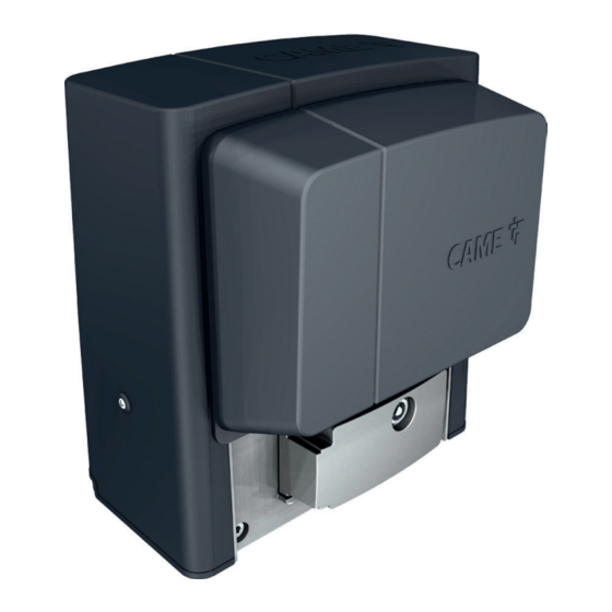
Page 5: Intended Use
400 kg that are up to 14 m in length. 801MS-0031 BX708ALS - Operator complete with control board with programming display, built-in radio decoder, movement and obstruction-detection device and mechanical limit switches for sliding gates weighing up to 800 kg that are up to 14 m in length. -
Page 6: Description Of Parts
Description of parts Operator Cover Control board Front cover Limit-switch tabs Gearmotor Transformer Capacitor Release hatch Mechanical limit switch Fixtures and fittings Anchoring plate Assembly brackets for housing accessories (optional) Control board holder... - Page 7 Control board The functions on the input and output contacts, the time settings and user management are set and viewed on the display. All connections are protected by quick fuses. For the system to work properly, before fitting any plug-in card, DISCONNECT THE MAIN POWER SUPPLY and remove any batteries. Before working on the control panel, disconnect the mains power supply and remove the batteries, if any.
-
Page 8: Usage Limitations
Size Usage limitations MODELS BX704AGS BX708AGS BX704ALS BX708ALS BX708RGS Pinion module Maximum gate-leaf length (m) Maximum gate-leaf weight (kg) Technical data MODELS BX704AGS BX708AGS BX704ALS BX708ALS BX708RGS Power supply (V - 50/60 Hz) 230 AC 230 AC 230 AC 230 AC... -
Page 9: Operating Cycles
The operating cycle calculation considers a gate that is of standard length (the sliding part), professionally installed, free of any mechanical issues and/or accidental friction points, and measured at an ambient temperature of 20°C, as stated in EN standard 60335-2-103. MODELS BX704AGS BX708AGS BX704ALS BX708ALS BX708RGS Cycles/hour (no.) Consecutive cycles (no.) Standard reference length of the sliding part (m) For gates where the sliding part is of a different length to the standard measurement, please see the graphs. - Page 10 Cable types and minimum thicknesses Cable length (m) up to 20 from 20 to 30 Power supply 230 V AC 3G x 1.5 mm2 3G x 2.5 mm2 Flashing beacon 230 V AC 2 x 1.5 mm2 2 x 1.5 mm2 TX Photocells 2 x 0.5 mm2 2 x 0.5 mm2...
-
Page 11: Installation
INSTALLATION The following illustrations are examples only. The space available for fitting the operator and accessories varies depending on the area where it is installed. It is up to the installer to find the most suitable solution. The drawings show an operator fitted on the left. Preliminary operations Dig a hole for the foundation frame. - Page 12 Insert the screws supplied in the anchoring plate. Lock the screws in place with the nuts supplied. Remove the pre-shaped clamps using a screwdriver. Fit the anchoring plate in the iron cage. The tubes must pass through the existing holes. UNI 5739 12 X 70 Position the anchoring plate, taking note of the measurements shown in the drawing.
- Page 13 Remove the nuts from the screws. Insert the electrical cables into the tubes until they protrude by about 600 mm. Setting up the operator Remove the front cover. Remove the operator cover.
- Page 14 Place the operator on top of the anchoring plate. The electrical cables must pass under the operator foundation frame Lift the operator by 5-10 mm from the plate by adjusting the threaded feet, to allow for any adjustments that may need to be made between the rack and pinion. Fastening the rack Release the operator.
- Page 15 Adjusting the pinion-rack coupling Open and close the gate manually. Adjust the pinion-rack coupling distance using the threaded feet (vertical adjustment) and the holes (horizontal adjustment). The weight of the gate must not bear down upon the operator. Fastening the operator in place Only fasten the operator after adjusting the pinion-rack coupling.
- Page 16 Determining the travel end points with mechanical limit switches Open the gate. Insert the opening limit-switch tab in the rack. The spring must trigger the microswitch. Fasten the opening limit-switch tab using the grub screws supplied. ~ 20 mm Close the gate. Insert the closing limit-switch tab in the rack.
-
Page 17: Electrical Connections
ELECTRICAL CONNECTIONS Passing the electrical cables Connect all wires and cables in compliance with the law. The electrical cables must not touch any parts that may overheat during use (such as the motor and transformer). Use cable glands to connect the devices to the control panel. One of these must be used exclusively for the power supply cable. Cable glands on the board holder Power supply Make sure the mains power supply is disconnected during all installation procedures. -
Page 18: Signalling Devices
Power supply output for accessories The output normally delivers 24 V AC. The sum of the power draw for the connected accessories must not exceed 20 W. Torque limiter White cable Black cable Red cable Blue cable Purple cable Orange cable To vary the motor torque, move the corresponding Faston terminal to one of the four positions;... -
Page 19: Command And Control Devices
Command and control devices Keypad selector Card reader Transponder selector switch STOP button (NC contact) Stop the gate and exclude automatic closing. Use a control device to resume movement. If the contact is not used, it must be deactivated during programming. Control device (NO contact) PARTIAL OPENING function Control device (NO contact) - Page 20 DIR / DELTA-S photocells DIR / DELTA-S photocells Standard connection Connection with safety test See function F5, safety devices test. 2 TX C NC TX 2 2 TX C NC TX 2 DFWN sensitive edge C NO NC DFWN...
-
Page 21: Getting Started
PROGRAMMING Programming button functions ESC button The ESC button is used to perform the operations described below. Exit the menu Delete the changes Go back to the previous screen Stop the operator < > buttons The <> buttons are used to perform the operations described below. Navigate the menu Increase or decrease values Open or close the operator... - Page 22 CY input Associate a function with the CY input. CY input OFF (Default) C1 = Reopen while closing (photocells) C2 = Reclose while opening (photocells) C3 = Partial stop Only with [Automatic close] activated. C4 = Obstacle standby (photocells) C7 = Reopening during closure (sensitive edges) C8 = Reclose while opening (sensitive edges) R7 = Reopen while closing (sensitive edges with 8K2 resistor) R8 = Reclose while opening (sensitive edges with 8K2 resistor)
- Page 23 Sensor type Set the type of control device. Sensor type 0 = Transponder selector switch 1 = Keypad selector (default) Additional light Choose the operating mode of the lighting device connected to the output. Additional light 0 =Flashing beacon (Default) 1 = Cycle light.
- Page 24 Slowdown sensitivity Adjust the obstacle-detection sensitivity level during slowdown. This function appears only if the [Encoder] function is active. Slowdown sensitivity 10% to 100% (Default 100%) - 10% = maximum sensitivity - 100% = minimum sensitivity Partial opening point Determine the gate partial opening point, as a percentage of total travel. This function appears only if the [Encoder] function is active.
- Page 25 Transferring MASTER-SLAVE parameters Enable sharing for the parameters programmed on the master gate with the slave gate. This function appears only if the [RSE] function is active. Transferring MASTER-SLAVE OFF (Default) parameters Opening direction Set the gate opening direction. Opening direction 0 = To the left (default) 1 = To the right CRP address...
- Page 26 The operation can be carried out by using a transmitter or another control device. The boards that manage the control devices (AF - R700 - R800) must be inserted into the connectors. Download the LIST OF REGISTERED USERS form from the docs.came.com portal by typing in L20180423. New user...
- Page 27 Radio decoding Choose the type of radio coding for the transmitters enabled to control the operator. If you choose the type of radio coding for the transmitters [Rolling code] or [TW key block], any transmitters with a different type of radio coding saved previously will be deleted.
-
Page 28: Import/Export Data
Import/export data Save user data and system configuration data on a MEMORY ROLL card. The stored data can be reused for another control board to configure another system in the same way. Before inserting and removing the MEMORY ROLL card, DISCONNECT THE MAINS POWER SUPPLY TO THE LINE. Insert the MEMORY ROLL card into the corresponding connector on the control board. -
Page 29: Error Messages
ERROR MESSAGES Calibration error Adjustment error Encoder failure error Service test failure error Operating time error Open release-hatch error Check that the accessories fuse is not blown. Obstacle detected during closing Obstacle detected during opening The maximum number of obstacles detected consecutively has been exceeded Incompatible transmitter error Wireless system communication error Wireless system not configured error... - Page 30 PAIRED OPERATION Two connected operators are controlled with one command. Electrical connections Connect the two electronic boards with a UTP CAT 5 cable. Insert an RSE card into both control boards. Connect up the electrics for the devices and accessories. The devices and accessories must be connected to the control board which will be set as the MASTER.
- Page 31 Saving users All save user operations must be performed only on the control board set as the MASTER. Operating modes PARTIAL OPENING command STEP-BY-STEP or OPEN ONLY command MASTER SLAVE MASTER SLAVE MCBF Models BX704 BX708 14 m - 400 kg 150000 14 m - 800 kg 150000...
- Page 32 CAME S.p.A. Via Martiri della Libertà, 15 31030 Dosson di Casier Treviso - Italy Tel. (+39) 0422 4940 Fax (+39) 0422 4941...
Need help?
Do you have a question about the BX708ALS and is the answer not in the manual?
Questions and answers