
Related Manuals for SanRex SANARG 200AP


Summary of Contents for SanRex SANARG 200AP
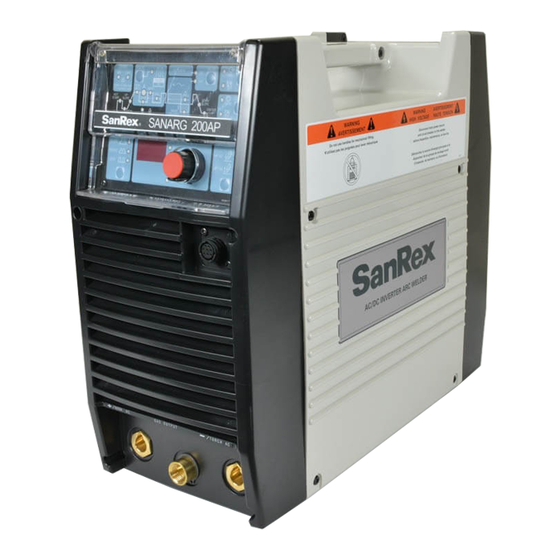
- Page 1 SanRex SANARG 200AP AC/DC INVERTER ARC WELDER Operators Manual Version No: B Issue Date: JUN 12, 2019 Manual No: K00A0316900...
- Page 3 Team! Dear Welding Professional, We would like to take this opportunity to thank you, and congratulate you on procuring a SanRex Model 200AP AC/DC STICK Welding Machine. Welding Professional, now that is a term that we do not take lightly. The welding machine that you purchased is a full function, portable unit that was designed with the Welding Professional in mind.
- Page 5 INTRODUCTION PURPOSE OF THIS MANUAL This manual has been prepared to present the safety, installation/operation and maintenance instructions for the Welding Machine Model 200AP, an AC/DC Stick and TIG welding machine manufactured by the Sansha Corporation of Osaka, Japan. The manual contains the information necessary for the Professional Welder to correctly use and operate the 200AP.
-
Page 6: Table Of Contents
Table of Contents SAFETY REGULATIONS AND REQUIREMENTS ............. 9 NOTES, CAUTIONS AND WARNING ANNOTATIONS ..........9 SAFETY RECOMMENDATIONS ..................10 WELDING SYMBOLS ....................... 11 1.3.1 SAFETY SYMBOL LEGEND ..................11 1.3.2 GRAPHIC SYMBOL LEGEND .................. 15 SAFETY PRECAUTIONS ....................16 SAFE OPERATION OF THE WELDER AND PERSONAL PROTECTION .... - Page 7 STICK WELDING ....................... 51 6.1.1 STICK SEQUENCE WITH VOLTAGE REDUCTION DEVICE DISABLED ..52 6.1.2 STICK SEQUENCE WITH VOLTAGE REDUCTION DEVICE ENABLED ..52 AC OR DC HF TIG WELDING ..................53 LIFT TIG SEQUENCE ......................54 6.3.1 STANDARD MODE ....................54 6.3.2 SLOPE MODE......................
-
Page 9: Safety Regulations And Requirements
SECTION 1- SAFETY REGULATIONS AND REQUIREMENTS Please read this operating manual thoroughly before utilizing the equipment. Wherever welding equipment is used, safety is always our concern. PROTECT yourself and others SAFETY REGULATIONS AND REQUIREMENTS Throughout this manual, notes, cautions, danger, attention and warnings are used to highlight important information. -
Page 10: Safety Recommendations
SAFETY RECOMMENDATIONS For the purpose of safety, it is recommended that this welding equipment be installed, maintained, inspected, and repaired by appropriable qualified person or persons who are well familiarized with welding equipment.. As for safety training, it is recommended to avail yourselves of various seminars and qualifying examinations for welding engineers and welding technicians sponsored by the Welding Society, the Welding Engineering Society, and the headquarters or branch offices of societies or associations concerned. -
Page 11: Welding Symbols
WELDING SYMBOLS 1.3.1 SAFETY SYMBOL LEGEND SYMBOL SOURCE OF HAZARD HOW TO AVOID HAZARD Don’t weld on painted parts. Remove the surface coating Welding Electric Shock before you begin welding. Keep Electrode your face away from the welding plume. Protect welding cables from sparks, hot metal, open flames, sharp edges, oil, and grease. - Page 12 SYMBOL SOURCE OF HAZARD HOW TO AVOID HAZARD Do not breathe fumes and gases. Keep your head out of the fumes. Chromium and Welding Fumes Use enough ventilation or Nickel Fumes exhaust at the arc or both to keep fumes and gases from your breathing zone and general area Maintain proper distances from the Arc Ray.
- Page 13 SYMBOL SOURCE OF HAZARD HOW TO AVOID HAZARD Establish a written policy documenting general safety Optical Radiation and requirements for the wearing of Thermal Arc Heat contact lenses. Conduct an eye hazard evaluation in the workplace Gloves should be: Dry and moisture resistant. Cuts, Scrapes, Heat, Mechanical, In good condition, no holes or...
- Page 14 SYMBOL SOURCE OF HAZARD HAZARD HOW TO AVOID Keep your head out of the fumes. Do not breathe the fumes. Any Coatings on Base Fumes and Use enough ventilation or Metal, Weld Process Gases exhaust at the arc, or both, to keep fumes and gases from your breathing zone and general area Be alert, aware, and focused on...
-
Page 15: Graphic Symbol Legend
1.3.2 GRAPHIC SYMBOL LEGEND STICK Amperage (Shielded Metal Arc SMAW) Voltage Pulse Current Function Hertz (cycles per second) Spot Time (GTAW) Remote Control Frequency (Panel/Remote) Seconds Remote Function Percentage Arc Control (SMAW) DC (Direct Current) Gas Post-Flow AC (Alternating Current) Gas Pre-Flow Voltage Reduction Standard Function... -
Page 16: Safety Precautions
SAFETY PRECAUTIONS ATTENTION CAUTION FOR PROPER USE, PLEASE READ THIS PROCEDURES, IF NOT PROPERLY OPERATING MANUAL THOROUGHLY FOLLOWED, MAY CAUSE A RISK TO PRIOR TO UTILIZING THE WELDING OPERATORS RESULTING IN MEDIUM MACHINE. OR SLIGHT INJURY AND/ OR DAMAGE The safety precautions described in Serious or light injury includes loss of this Operating Manual will give you the sight,... -
Page 17: Safe Operation Of The Welder And Personal Protection
SAFE OPERATION OF THE WELDER AND PERSONAL PROTECTION 1.5.1 IMPORTANT SAFETY PRECAUTIONS To prevent serious injury to the operator or others, be sure to observe the following: Never allow any unqualified Those heart person to enter the surrounding pacemakers should not enter the area of this welding equipment surrounding area... -
Page 18: Electric Shock
1.5.2 ELECTRIC SHOCK To prevent electric shock, be sure to observe the following precaution: Touching any parts that are electrically “live” or “hot” may Tighten cable connections cause fatal electric shock or securely and insulate it. burns. Have a qualified electrician Do not operate with welding connect the Welding Power equipment with its cover or... -
Page 19: Gases And Fumes
1.5.3 GASES AND FUMES To protect you and others from fumes and gases produced during the welding processes, use safeguards. Inhalation of gases and fumes produced during the welding When welding in confined processes can be dangerous and spaces, ensure that the welding hazardous to your health. -
Page 20: Fire And Explosions
1.5.4 FIRE AND EXPLOSIONS To prevent fire, explosion, or rupture, be sure to observe the following precautions Spatter or hot base metals Do not weld in the vicinity of produced during and flammable gases. immediately after the welding processes may cause fire. Keep base metals... -
Page 21: Arc Welding Rays, Noise And Spatter Or Slag
1.5.5 ARC WELDING RAYS, NOISE AND SPATTER OR SLAG To protect you and others from arc rays, scattered spatter or slag, and loud noise produced during the welding processes, use safeguards. Arc rays can cause your eyes To protect your eyes from irritation and burn your skin. -
Page 22: Gas Cylinders
1.5.6 GAS CYLINDERS To prevent the turnover of gas cylinder or the rupture of gas flow regulator, be sure to observe the following precautions Turnover of the gas cylinder may Read and follow all warnings, cause injury to the operator or safety precautions, others. -
Page 23: Reference Publications
REFERENCE PUBLICATIONS Refer to the following standards or their latest revisions for more information: 1. OSHA, SAFETY AND HEALTH STANDARDS, 29CFR 1910, obtainable from the Superintendent of Documents, U.S. Government Printing Office, 732 N. Capital St NW, Washington, D.C. 20402 2. - Page 24 PAGE LEFT INTENTIONALLY BLANK...
-
Page 25: Introduction And Description
WELDING MACHINE DESCRIPTION The SanRex model 200AP is an inverter based DC Power Source Unit that is powered from an external source of 208~230/460 VAC, single or three phase power. The 200AP models is capable of providing Constant Current (CC) output characteristics. The 200AP is... - Page 26 • Eliminates the possibility of the Tungsten Electrode to contaminate the base metal. This non-touch Arc-Start is suitable for code welding regulation. Save/Load of Welding Programs A total number of 5 welding programs can be saved into the SanRex 200AP memory. SAVEing the Current Weld Parameters into Memory •...
-
Page 27: Welding Output Voltage And Amperage Curves
WELDING OUTPUT VOLTAGE AND AMPERAGE CURVES 2.4.1 200AP V/A OUTPUT CURVES The waveforms shown in figure 2.1 are the maximum Voltage-Amperage output capabilities of the 200AP. Curves for actual welding setting will fall within the curves shown. 160A STICK PROCESS 200A LIFT-TIG PROCESS HF TIG PROCESS... -
Page 28: Functional Block Diagram
FUNCTIONAL BLOCK DIAGRAM Figure 2.2 shows the functional block diagram of the SanRex Model 200AP. FIGURE 2-2 : Model 200AP Functional Block Diagram... -
Page 29: Installation Recommendations
SECTION 3- INSTALLATION RECOMMENDATION INSTALLATION RECOMMENDATIONS TRANSPORTATION METHODS The case design of the 200AP incorporates a built-in handle for carrying purposes. The case design also allows for the units to be stacked where the feet on one unit aligns with the notches on the top of another unit. WARNING: ELECTRIC SHOCK can kill. -
Page 30: Environment
ENVIRONMENT The SANARG 200AP model is designed for use in adverse environments with an IP23S rating. Examples of environments with increased adverse conditions are - • With its small, lightweight and portable form factor, the 200AP is ideal for use in locations in which freedom of movement is restricted, so that the operator is forced to perform work in cramped (kneeling, sitting or lying) positions. -
Page 31: High Frequency Interference
WARNING: Explosives: The high frequency section of this machine has an output similar to a radio transmitter. The machine should NOT be used in the vicinity of blasting operations due to the danger of premature firing. WARNING: Computers: It is also possible that operation close to computer installations may cause computer malfunction. -
Page 32: Location
Re-radiation from Unearthed Metallic Objects A major factor contributing to interference is re-radiation from unearthed metallic objects close to the welding leads. Remedy: Effective grounding of such objects will prevent re-radiation in most cases. LOCATION The location of the 200AP unit should be in accordance to the following guidelines: •... -
Page 33: Fusing
3.5.2 FUSING The 200AP unit is equipped with an input switch and does not have and input circuit breaker for protection. It is the responsibility of the user to provide proper fuse protection for the welding power source. Failure to do so will void the warranty. The installer should reference the table above to select a suitable fuse for the input voltage of the installation location. -
Page 34: 200Ap Input Power Connections
3.5.3.1 200AP Input Power Connections NOTE: The 200AP is equipped with a three-conductor with earth power cable that is connected at the welding power source end for single and three phase electrical input power. For Single-Phase operation connect the GREEN, BLACK and WHITE input conductors. - Page 35 Figure 3-2. Electrical Input Connections 200AP...
-
Page 36: Specifications
37 lb. (17 kg) SanRex continuously strives to produce the best product possible and therefore reserves the right to change, improve or revise the specifications or design of this or any product without prior notice. Such updates or changes do not entitle the buyer of equipment previously sold or shipped to the corresponding changes, updates, improvements or replacement of such items. -
Page 37: General
3.6.2 GENERAL Model IA-2000TP-U2E General Approval/Standard IEC60974-1,IP23S Language English Front Panel Front Panel Pot Welding Current / Parameters Adjustment Push to voltage display Function Select Button Process STICK / HF TIG / LIFT TIG OUTPUT STD / SLOPE / REPEAT / SPOT Mode AC/DC AC / DC... -
Page 38: Duty Cycle
DUTY CYCLE The duty cycle of a welding power source is the percentage of a ten (10) minute period that it can be operated at a given output without causing overheating and damage to the unit. If the welding amperes decrease, the duty cycle increases. If the welding amperes are increased beyond the rated output, the duty cycle will decrease. -
Page 39: Operator Controls, Dimensions & Outline
SECTION 4- OPERATOR CONTROLS, DIMENSIONS & OUTLINE OPERATOR CONTROLS, DIMENSIONS & OUTLINE DIMENSIONS AND OUTLINE The figure below shows the dimensions and the outline of the SanRex model 200AP. FIGURE 4-1 : Model 200AP Dimensions and Controls OPERATOR CONTROLS, LOCATION AND FUNCTIONALITY Refer to the figure above for the corresponding reference numbers. - Page 40 3. Positive Output Terminal Welding current flows from the Power Source via heavy duty Dinse type terminal. It is essential, however, that the male plug is inserted and turned securely to achieve a sound electrical connection. A loose or worn connection will cause excessive heat and may cause damage to the front frame or internal components of the welding unit.
- Page 41 7. AC Input Voltage Select Switch This manual slide, user selectable switch selects the proper AC input voltage range. If this slide switch is not set to the position that matches the input line voltage, the internal microcontroller will inhibit the welding power source from turning on and will display an error code on the front control display panel.
-
Page 42: 14-Pin Remote Control Receptacle
14-PIN REMOTE CONTROL RECEPTACLE FIGURE 4-2 : 14-PIN Remote Control Receptacle Layout. Socket Function Input Torch Switch Input. To energize weld current, connect pins A & B. Input Torch Switch Input. To energize weld current, connect pins A & B. Output +10VDC signal connects to high side of 1k ohm remote control potentiometer. -
Page 43: Parameter Display Panel
PARAMETER DISPLAY PANEL Figure 4.3 – 200AP Front Panel Parameter Description This parameter operates in TIG modes only and is used to get gas to the weld zone prior to striking the arc, once the torch trigger switch has been pressed. - Page 44 Parameter Description PEAK CUR. This parameter sets the PEAK weld current when in PULSE mode (WELD) This parameter sets the TIG WELD current in STD, SLOPE, REPEAT and SPOT modes when PULSE is off. This parameter also sets the STICK weld current.
- Page 45 Parameter Description The SAVE/LOAD buttons are used to save and retrieve a total number of 5 programs into the 200AP memory. SAVE the Current Weld Parameters into Memory • Press the SAVE button SAVE/LOAD • Select a memory location by rotating the control knob, 1 to 5 is displayed on the meter.
-
Page 46: Function Selection
FUNCTION SELECTION The Table below provides information of the functions that are available using the front panel display. Description Function Selection STICK LIFT 2T operation in TIG Modes using remote devices to control contactor & current 4T operation in TIG Modes with crater SLOPE fill using a remote contactor device to control sequence. -
Page 47: Parameter Selection
PARAMETER SELECTION The Table below provides information of the parameters that are available for modification using the front panel display. The table also provides information on the ranges available for each parameter as well as to which weld process the parameter is available. Process PARAMETER RANGE... -
Page 48: Set-Up For Basic Stick (Smaw) And Tig (Gtaw) Welding
SECTION 5- SET-UP FOR BASIC STICK (SMAW) AND TIG (GTAW) WELDING SET-UP FOR BASIC STICK (SMAW) AND TIG (GTAW) WELDING Conventional operating procedures apply when using the Welding Power Source, i.e. connect work lead directly to work piece and electrode lead is used to hold electrode. Wide safety margins provided by the coil design ensure that the Welding Power Source will withstand short- term overload without adverse effects. -
Page 49: Sequence Of Operation
SECTION 6 – SEQUENCE OF OPERATION SEQUENCE OF OPERATION NOTE: Scroll Buttons are used to select the parameters to be set. The LED’s show which function is being adjusted on the weld sequence graph. Refer to Symbols Table located in the front of the manual for Symbol descriptions. - Page 50 1. Pulse Function – Pressing this button enables the TIG current pulse functions. 2. Remote Current Function – Pressing this buttons enables remote current functions. 3. TIG Mode Functions – Pressing this button scrolls through the output TIG function modes. The user can select between Standard, Slope, Slope w/repeat or Spot modes.
-
Page 51: Stick Welding
STICK WELDING • Connect work lead to negative terminal • Connect electrode lead to positive terminal • Switch machine on • Set AC or DC weld current. If AC is selected then set AC FREQ to 60Hz & WAVE BALANCE to 50%. •... -
Page 52: Stick Sequence With Voltage Reduction Device Disabled
6.1.1 STICK SEQUENCE WITH VOLTAGE REDUCTION DEVICE DISABLED Hot cur. Arc control Output Current Hot start Output Voltage Arc control level (about 18V) 6.1.2 STICK SEQUENCE WITH VOLTAGE REDUCTION DEVICE ENABLED I_DET Hot cur. Arc control Output Current Hot start Output Voltage Arc control level (about 18V) -
Page 53: Ac Or Dc Hf Tig Welding
AC OR DC HF TIG WELDING • Connect work lead to positive terminal • Connect TIG torch to negative terminal • Switch machine on • Set AC or DC weld current. If AC is selected then set AC FREQ & WAVE BALANCE •... -
Page 54: Lift Tig Sequence
LIFT TIG SEQUENCE 6.3.1 STANDARD MODE Contactor short Electrode short Solenoid Post flow time Pulse width Post flow time Pre flow time Pulse frequency Output current Peak cur. Base cur. 25A (fixed) Lift only. 6.3.2 SLOPE MODE Contactor short short Electrode Solenoid Output current... -
Page 55: Hf Tig Sequence
HF TIG SEQUENCE 6.4.1 STANDARD MODE Contactor Solenoid Post flow time Pre flow time Pulse width Hot start Hot cur. Pulse frequency Output current Peak cur. Base cur. 6.4.2 SLOPE MODE Contactor Solenoid Output current Initial cur. Crater cur. Up slope time Down slope time 6.4.3 REPEAT MODE Contactor... -
Page 56: Spot Mode
6.4.4 SPOT MODE Contactor Solenoid Pre flow time Spot time Hot start Hot cur. Output current... -
Page 57: Voltage Reduction Device (Vrd)
SECTION 7 – VOLTAGE REDUCTION DEVICE VOLTAGE REDUCTION DEVICE (VRD) The 200AP unit is equipped with a Voltage Reduction Device circuit that when enabled lowers the Open Circuit Voltage (OCV) in STICK mode. This function is used in applications where a high OCV in STICK mode is dangerous or applications where a lower OCV would be advantageous. - Page 58 Remove four mounting screws from the control panel (see Figure 7-2). b) Access the VRD control by gently prying back the front panel controls to reveal the VRD on/off potentiometer (see Figure 7-2). Do not pull back the front panel with excessive force as this may unplug the control PCB.
- Page 59 Figure 7-3 VRD ON/OFF Step D c) Turning the VRD ON/OFF (see Figure 7-3). • To turn VRD ON: rotate the trim potentiometer (VR1) on the display PCB fully clockwise. When VRD is turned ON check that it operates as per VRD Specifications.
- Page 60 PAGE LEFT INTENTIONALLY BLANK...
-
Page 61: Trouble Shooting
SECTION 8 – TROUBLE SHOOTING TROUBLE SHOOTING POWER SOURCE PROBLEMS Description Possible Cause Remedy 1 The welding arc The Primary supply voltage Switch ON the Primary cannot be has not been switched ON. supply voltage. established. The Welding Power Source Switch ON the Welding switch is switched OFF. - Page 62 Description Possible Cause Remedy 5 Gas flow won’t A Weld Mode (STD, SLOPE, A Strike an arc to complete the shut off. REPEAT or SPOT) was weld cycle. changed before POST-FLOW gas time had finished. Switch machine off then on to reset solenoid valve sequence.
-
Page 63: Power Source Error Codes
80ºC for E01 resets when TH1 decreases B. Fan ceases to operate. B. Have an Accredited SanRex about 1 second. to 70ºC for about 30 seconds. Service Agent investigate. C. Air flow is restricted by vents C. - Page 64 Description Possible Cause Remedy Remarks E11 error code displayed Primary supply voltage is Have an Accredited SanRex Weld current ceases. Over Primary supply greater than the nominal Service Agent or a qualified Buzzer sounds constantly. (input) voltage at primary voltage plus 10%.
- Page 65 Mains supply (input) voltage Have an Accredited off but control circuit has and then switch on to reset E99 error. has been turned off. SanRex Service Agent or a power from the primary qualified electrician check capacitors. the Mains voltage and...
- Page 66 PAGE LEFT INTENTIONALLY BLANK...
-
Page 67: Routine Maintenance
SECTION 9- ROUTINE MAINTENANCE ROUTINE MAINTENANCE Routine inspection and testing (power source) An inspection of the power source, an insulation resistance test and an earth resistance test should be carried out a) For transportable equipment, at least once every 3 months; and b) For fixed equipment, at least once every 12 months. -
Page 68: Opening The Enclosure
OPENING THE ENCLOSURE 1) Confirm that the switch of power supply and the switch on switchboard (distribution panel) are all OFF. The capacitors inside the power supply will slowly discharged after you turn off the switch of the power supply or the switch at the breaker box (distribution panel). - Page 69 3) Loosen the screws on the front panel and the rear panel by turning them approximately two turns CCW. NOTE: DO NOT remove the screws completely. 4) Pull the front panel slightly forward and pull the rear panel slightly backward. The interlocking hooks of the side case covers can now be disengaged from the front and rear panels...
- Page 70 5) Remove the side covers. 6) Remove protection cover sheet by removing the plastic tabs. NOTE: When you re-assemble the parts, conduct the above process backwards.
-
Page 71: Parts List 200Ap
SECTION 10- PARTS LIST 10.0 PARTS LIST 200AP... - Page 79 PAGE LEFT INTENTIONALLY BLANK...
-
Page 80: Interconnect Diagram 200Ap
10.1 INTERCONNECT DIAGRAM 200AP... -
Page 82: Exploded View 200Ap
10.2 EXPLODED VIEW 200AP... - Page 84 PAGE LEFT INTENTIONALLY BLANK...
-
Page 85: Appendix A: 200Ap Quick Set-Up Guide
APPENDIX A: 200AP QUICK SET-UP GUIDE SANARG 200AP Front Panel Description STICK Process Functions – Push the Process button to scroll through the three processes (STICK, LIFT TIG, HF TIG). The green LED will HF TIG light as the process is selected. When in STICK mode, the output contactor is activated. - Page 86 Detailed description of each parameter can be found in the Owner’s Manual. SANARG 200AP SETTINGS The settings shown below should be used as guidelines for a first set-up. The welder should adjust these setting to achieve optimal weld performance for the specific application.
- Page 87 200AP QUICK SET-UP GUIDE SANARG 200AP Front Panel Description STICK Process Functions – Push the Process button to scroll through the three processes (STICK, LIFT TIG, HF TIG). The green LED will HF TIG light as the process is selected. When in STICK mode, the output contactor is activated.
- Page 88 Detailed description of each parameter can be found in the Owner’s Manual. SANARG 200AP SETTINGS The settings shown below should be used as guidelines for a first set-up. The welder should adjust these setting to achieve optimal weld performance for the specific application.
- Page 89 PAGE LEFT INTENTIONALLY BLANK...
- Page 90 SanRex SANREX CORPORATION (USA) SANSHA ELECTRIC MFG. CO. LTD. (Japan) 50 Seaview Blvd. 301056, Nishi-Awaji, Higashiyodogawa Port Washington NY 11050 Osaka Japan 533-0031...
Need help?
Do you have a question about the SANARG 200AP and is the answer not in the manual?
Questions and answers