Table of Contents
Advertisement
Advertisement
Table of Contents

Related Manuals for Ubiquiti LiteBeam 5AC Gen 2


Summary of Contents for Ubiquiti LiteBeam 5AC Gen 2
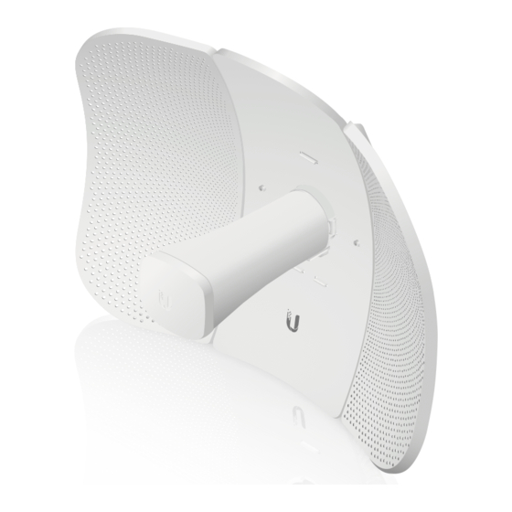
- Page 1 5 GHz airMAX ac Radio with ® InnerFeed Technology ® Model: LBE-5AC-Gen2...
-
Page 2: Package Contents
Mounting Bracket Products may be different from pictures and are subject to change without notice. TERMS OF USE: Ubiquiti radio devices must be professionally installed. Shielded Ethernet cable and earth grounding must be used as conditions of product warranty. TOUGHCable ™... -
Page 3: Installation Requirements
AC ground of the PoE. We recommend that you protect your networks from harmful outdoor environments and destructive ESD events with industrial‑grade, shielded Ethernet cable from Ubiquiti Networks. For more details, visit www.ubnt.com/toughcable Application Examples The LiteBeam AC mounted outdoors with the reflector installed provides directional outdoor coverage (gain reflector‑dependent). -
Page 4: Hardware Overview
Hardware Overview Bottom View Technology LEDs Reset Button Ethernet Port Antenna Feed Re ector Assembly Securing Arms Port Cover Feed Receiver Elevation Mount Azimuth Mount... - Page 5 LEDs Ethernet The LED will light steady blue when an active Ethernet connection is made and flash when there is activity. Power The LED will light blue when the device is connected to a power source. Button Reset To reset to factory defaults, press and hold the Reset button for more than 10 seconds while the LiteBeam AC is powered on.
-
Page 6: Hardware Installation
Hardware Installation The LiteBeam AC was designed for outdoor use and quick mounting on a pole. 1. Assemble the antenna reflector by attaching the Side Reflector Panels to the Center Reflector Panel: a. Insert the heads of the two mounting studs on the Center Reflector Panel into the large opening of the slotted holes of the Side Reflector Panel. - Page 7 2. Hold the reflector assembly by hand (do not use a tabletop or flat surface) and insert the Feed Receiver into the reflector assembly to secure the panels: a. Align the arrows on the Center Reflector Panel and the Feed Receiver, and insert both edges of the Side Reflector Panels and Center Reflector Panels into the Securing Arms of the Feed Receiver.
- Page 8 WARNING: Do not install the Feed Receiver into the reflector assembly by pushing down onto a tabletop or other flat surface as this can deform the panels. Hold the reflector assembly by hand. c. For additional support, there are eight machine screws that secure the Side Reflector Panels to the antenna assembly.
- Page 9 3. Insert the Antenna Feed into the Feed Receiver until the feed locks into place. 4. Turn the Port Cover counterclockwise to reveal the Ethernet Port on the Antenna Feed.
- Page 10 5. Take one end of an Ethernet cable and push it through the rubber housing on the Port Cover and connect it to the Ethernet Port. 6. Reattach the Port Cover to the Feed Receiver by turning it clockwise until it is secure.
-
Page 11: Pole Mounting
Pole Mounting 1. Attach the Elevation Mount to the Feed Receiver by lining up the notches with the pins on the Feed Receiver and pressing forward until the Elevation Mount snaps on. 2. Open the Metal Strap and feed it through the slot of the Azimuth Mount. - Page 12 3. Wrap the Metal Strap around the pole. Use a 7 mm socket wrench or screwdriver to turn the screw clockwise and securely fasten the strap to the pole. 4. Attach the Elevation Mount to the Azimuth Mount as shown below.
- Page 13 5. Aim the Antenna Feed toward the other end of the wireless link. Use the bubble level on the back of the Feed Receiver to ensure proper level alignment. 6. Lock the aim by hand‑tightening the Wingnuts clockwise on both the Elevation Mount and the Azimuth Mount.
-
Page 14: Connecting Power
Connecting Power 1. Connect the Ethernet cable from the LiteBeam AC to the POE port on the Power Adapter. 2. Connect an Ethernet cable from your LAN to the LAN port on the Power Adapter. 3. Connect the Power Cord to the Power Adapter, and then plug the Power Cord to a power outlet. - Page 15 2. Connect your device’s Wi‑Fi to the LiteBeam AC SSID named: LBE-5AC-Gen2:<MAC Address> Note: Ensure that DHCP is enabled on your Wi‑Fi adapter. 3. Launch the app. 4. Tap the LiteBeam 5AC on the Connections screen. LiteBeam 5AC Gen 2 192.168.1.20 LBE-5AC-Gen2...
- Page 16 5. Tap Connect on the Login screen. LiteBeam 5AC Gen 2 LBE-5AC-Gen2:F09FC25EXXXX 6. Select your Country and tap Done. United Kingdom Argentina Armenia Aruba Australia Austria Azerbaijan Bahrain Barbados Belarus 7. Under Configuration, customize your settings as needed. LiteBeam 5AC Gen2...
-
Page 17: Web Portal
Web Portal 1. Connect your device’s Wi‑Fi to the LiteBeam 5AC SSID named: LBE-5AC-Gen2:<MAC Address> Note: Ensure that your Wi‑Fi connection has DHCP enabled. 2. Launch a web browser and go to: http://setup.ubnt.com 3. Enter ubnt in the Username and Password fields. Select your Country and Language. -
Page 18: Installer Compliance Responsibility
Installer Compliance Responsibility Devices must be professionally installed and it is the professional installer's responsibility to make sure the device is operated within local country regulatory requirements. The Output Power field is provided to the professional installer to assist in meeting regulatory requirements. -
Page 19: Specifications
Specifications LBE‑5AC‑Gen2 Dimensions 358 x 271.95 x 272.50 mm (14.09 x 10.71 x 10.73") Weight With Mount 980 g (2.16 lb) Without Mount 800 g (1.76 lb) Networking Interface (1) 10/100/1000 Ethernet Port Antenna Gain 23 dBi Max. Power Output 25 dBm Max. -
Page 20: Safety Notices
Safety Notices Read, follow, and keep these instructions. Heed all warnings. Only use attachments/accessories specified by the manufacturer. WARNING: Do not use this product in location that can be submerged by water. WARNING: Avoid using this product during an electrical storm. -
Page 21: Limited Warranty
Ubiquiti MAC label, or is missing any other original Ubiquiti label(s); or (VII) has not been received by Ubiquiti within 30 days of issuance of the RMA. In addition, the above warranty shall apply only if: the product has been properly installed and used at all times in accordance, and in all material respects, with the applicable Product documentation;... -
Page 22: Limitation Of Liability
SUBJECT TO LIMITATIONS, INTERRUPTIONS, DELAYS, CANCELLATIONS AND OTHER PROBLEMS INHERENT IN THE USE OF COMMUNICATIONS FACILITIES. UBIQUITI NETWORKS, ITS AFFILIATES AND ITS AND THEIR THIRD PARTY PROVIDERS ARE NOT RESPONSIBLE FOR ANY INTERRUPTIONS, DELAYS, CANCELLATIONS, DELIVERY FAILURES, DATA LOSS, CONTENT CORRUPTION, PACKET LOSS, OR OTHER DAMAGE RESULTING FROM ANY OF THE FOREGOING. -
Page 23: Industry Canada
MANDATORY STATUTORY RIGHTS APPLICABLE TO THE LICENSE OF ANY SOFTWARE (EMBEDDED IN THE PRODUCT) TO YOU. The United Nations Convention on Contracts for the International Sale of Goods shall not apply to any transactions regarding the sale of the Products. Compliance Changes or modifications not expressly approved by the party responsible for compliance could void the user’s authority to operate the equipment. -
Page 24: Australia And New Zealand
This radio transmitter (6545A‑LBE5ACG2) has been approved by Industry Canada to operate with the antenna types listed below with the maximum permissible gain and required antenna impedance for each antenna type indicated. Antenna types not included in this list, having a gain greater than the maximum gain indicated for that type, are strictly prohibited for use with this device. - Page 25 CE Marking CE marking on this product represents the product is in compliance with all directives that are applicable to it. Alert Sign (!) Follows CE Marking Alert sign must be indicated if a restriction on use applied to the product and it must follow the CE marking.
- Page 26 Español La Directiva 2012/19/UE exige que los equipos que lleven este símbolo en el propio aparato y/o en su embalaje no deben eliminarse junto con otros residuos urbanos no seleccionados. El símbolo indica que el producto en cuestión debe separarse de los residuos domésticos convencionales con vistas a su eliminación.
-
Page 27: Declaration Of Conformity
[German] Anforderungen und den anderen relevanten Vorschriften der Richtlinie 1999/5/EG befindet. Ελληνική Δια του παρόντος, UBIQUITI NETWORKS, δηλώνει ότι αυτή η συσκευή UBIQUITI NETWORKS, είναι σε συμμόρφωση με τις [Greek] βασικές απαιτήσεις και τις λοιπές σχετικές διατάξεις της οδηγίας 1995/5/ΕΚ. -
Page 28: Online Resources
. u b n t . c o m ©2016‑2017 Ubiquiti Networks, Inc. All rights reserved. Ubiquiti, Ubiquiti Networks, the Ubiquiti U logo, the Ubiquiti beam logo, airMAX, airOS, InnerFeed, LiteBeam, and TOUGHCable are trademarks or registered trademarks of Ubiquiti Networks, Inc.
Need help?
Do you have a question about the LiteBeam 5AC Gen 2 and is the answer not in the manual?
Questions and answers
Как настроить в режиме моста