Ubiquiti airFiber AF-5XHD Manual
Hide thumbs
Also See for airFiber AF-5XHD:
- Quick start manuals (33 pages) ,
- Quick start manual (29 pages) ,
- Quick start manual (46 pages)
Table of Contents
Advertisement
Package Contents
airFiber AF-5XHD
Metal Strap
IP67 Upgrade Kit
(Vent and Gasket)
Antenna Compatibility
The airFiber AF-5XHD radio is designed for use with the following airFiber X
antenna models:
AF-5G23-S45
AF-5G30-S45
AF-5G34-S45
The AF-5XHD can also operate with the following RocketDish™ antenna models:
RD-5G30*
GPS Antenna Mount
Zip Ties (Qty. 2)
Gigabit PoE (24V, 1A) with
Mounting Bracket
External GPS Antenna
Universal Bracket
Power Cord
Advertisement
Table of Contents

Related Manuals for Ubiquiti airFiber AF-5XHD


Summary of Contents for Ubiquiti airFiber AF-5XHD
- Page 1 Gigabit PoE (24V, 1A) with Power Cord (Vent and Gasket) Mounting Bracket Antenna Compatibility The airFiber AF-5XHD radio is designed for use with the following airFiber X antenna models: AF-5G23-S45 AF-5G30-S45 AF-5G34-S45 The AF-5XHD can also operate with the following RocketDish™ antenna models:...
-
Page 2: Installation Requirements
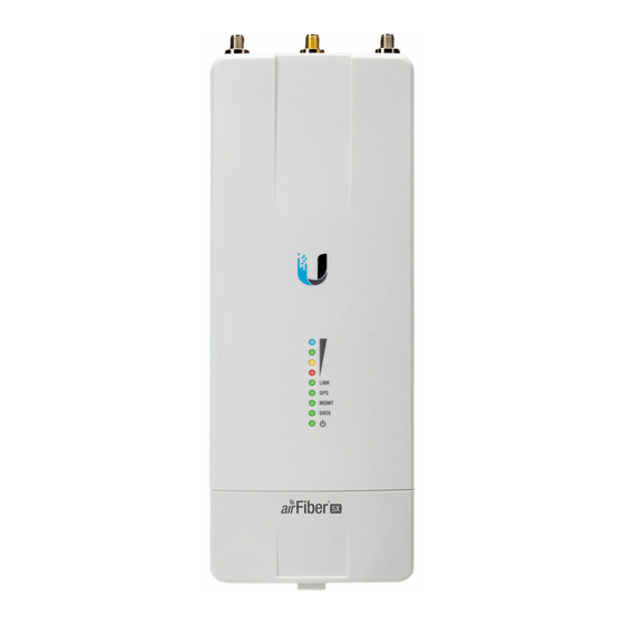
RD-5G34* * Requires Universal Bracket (included) or AF-5G-OMT-S45 Conversion Kit (not included). Installation Requirements Clear line of sight between airFiber radios Clear view of the sky for proper GPS operation Vertical mounting orientation Mounting point: At least 1 m below the highest point on the structure For tower installations, at least 3 m below the top of the tower Ground wires –... - Page 3 airFiber Antenna Connectors Used to attach RF antenna cables (not included). GPS Antenna Connector Used to attach the GPS Antenna. Signal LEDs Signal 4 LED will light blue when on. Signal 3 LED will light green when on.
- Page 4 Signal 2 LED will light yellow when on. Signal 1 LED will light red when on. Bootup to airOS When powering on, the Power, GPS, Link, and Signal 1-4 LEDs light on. Once the CPU code takes over, the GPS, Link, and Signal 1-3 LEDs turn off.
-
Page 5: Installation Overview
No GPS Synchronization Non-Operational (Weak Signal) Operational (Strong Signal) MGMT LED No Ethernet Link Ethernet Link Established Random Flash Ethernet Activity Data LED No Ethernet Link Ethernet Link Established Random Flash Ethernet Activity Power LED No Power Powered On Management Port 10/100/1000 Mbps, secured Ethernet port for configuration. -
Page 6: Connecting Power Over Ethernet
We recommend that you configure your paired AF-5XHD radios before site installation. The overview below summarizes the installation procedure, and the subsequent sections provide detailed installation information. Connect the airFiber PoE Adapter to the Data port, and connect your computer to the MGMT port. -
Page 7: Airfiber Configuration
WARNING: Use only the included adapter, model POE-24V-5X-HD. Failure to do so can damage the unit and void the product warranty. airFiber Configuration The instructions in this section explain how to access the airFiber Configuration Interface and configure the following settings: Wireless Mode Configure one AF-5XHD as the Master and the other as the Slave. - Page 8 There are two methods for configuration: Ubiquiti® Network Management System (preferred method) airFiber Configuration Interface (browser-based interface) Configuration Using UNMS 1. Launch the UNMS app. 2. Optional: Enable Bluetooth on your mobile device. Note: By default, Bluetooth is enabled on the AF-5XHD.
- Page 9 Note: UNMS screens shown here are from the iOS-based app. The Android-based app differs slightly in appearance and operation. 6. Configure these settings: a. On one AF-5XHD, enable Master Mode; on the other AF-5XHD, keep the default setting (Off) for Master Mode. b.
- Page 10 e. In the Security Key field, enter a combination of alphanumeric characters (0- 9, A-Z, or a-z). Note: The key is an alphanumeric password between 8 and 63 characters long. 7. Click Save Changes. 8. Configure each airFiber radio with a unique IP address for the Data port: a.
- Page 11 Configuration Using Browser-Based Interface 1. Optional (if the Data port is used for power only): 2. Configure the Ethernet adapter on your computer with a static IP address on the 192.168.2.x subnet. 3. Launch your web browser. In the address field, type the address of the port you are using to manage the device: http://192.168.2.20 (Management port) http://192.168.1.20 (Data port)
- Page 12 Click Save Changes. Repeat the instructions in the airFiber Configuration section on the other AF-5XHD radio. For details on the airFiber Configuration Interface, refer to the airFiber AF-5XHD User Guide, available at: ui.com/download/airfiber Upgrade for IP67 Compliance...
- Page 13 Note: Do not damage or remove the post on the Port Cover.
-
Page 14: Hardware Installation
Hardware Installation Installing the Ground Wire... - Page 15 3. At the installation site, secure the other end of the ground wire to a grounded mast, pole, tower, or grounding bar. WARNING: Failure to properly ground your airFiber radio will void your warranty. Note: The ground wire should be as short as possible and no longer than one meter in length.
- Page 18 Mount to a RocketDish Antenna Note: If you are mounting the AF-5XHD on a RocketDish equipped with the AF-5G-OMT-S45 Conversion Kit, the Universal Bracket is not needed. Refer instead to the Mount to an airFiber X Antenna section for instructions. The RocketDish RD-5G30 antenna is shown in this section:...
- Page 19 Mount the External GPS Antenna Locate a mounting point that has a clear view to the sky, and is above and as far away as possible from the AF-5XHD. 1. ...
- Page 20 Connecting Power over Ethernet 2. ...
-
Page 21: Surge Protection
Optional Surge Protection For added protection, install two surge suppressors, such as the Ubiquiti Ethernet Surge Protector, model ETH-SP, at the end of each link. Install the first surge protector within one meter of the airFiber Data port, and install the second surge... -
Page 22: Establishing A Link
Alignment Tips To accurately align the airFiber radios for best performance, you MUST align only one end of the link at a time. You may need to use additional hardware to compensate for issues such as the improper orientation of a mounting pole or significant elevation differences between airFiber radios. - Page 23 Master Visually aim the Master at the Slave. To adjust the Master’s position, adjust the azimuth and the elevation. Adjust the azimuth:...
- Page 24 Note: Do NOT make simultaneous adjustments on the Master and Slave. Slave Visually aim the Slave at the Master. To adjust the Slave’s position, adjust the azimuth and elevation as described in step 1. 5. Check to see if a link is established. Ensure that the Link LED is solidly lit green and the Signal LEDs of the Slave are displaying signal levels.
-
Page 25: Installer Compliance Responsibility
8. Repeat steps 4 and 5 until you achieve an optimal link, with all four Signal LEDs solidly lit. This ensures the best possible data rate between the airFiber radios. 9. Lock the alignment on both airFiber antennas by tightening all the nuts and bolts. -
Page 26: Specifications
Antenna Frequency Gain Dish 5 GHz 34 dBi Specifications AF-5XHD Dimensions 224 x 82 x 48 mm (8.82 x 3.23 x 1.89") Weight 0.35 kg (12.3 oz) RF Connectors (2) RP-SMA Weatherproof (CH0, CH1) (1) SMA Weatherproof (GPS) GPS Antenna External, Magnetic Base Power Supply 24V, 1A PoE Gigabit Adapter (Included) -
Page 27: Safety Notices
Radio Frequency Accuracy < 2 ppm Channel Bandwidth 10/20/30/40/ 50/60/80/100 MHz Selectable Programmable Uplink and Downlink Duty Cycles Operating Frequency (MHz) Worldwide 4800 - 6200* US/CA U-NII-1 5150 - 5250 U-NII-2A 5250 - 5350 U-NII-2C 5470 - 5725 U-NII-3 5725 - 5850 Depends on regulatory region. -
Page 28: Limited Warranty
d. Protective earthing is provided by Listed AC adapter. Building installation shall provide appropriate short-circuit backup protection. e. Protective bonding must be installed in accordance with local national wiring rules and regulations. Limited Warranty ui.com/support/warranty The limited warranty requires the use of arbitration to resolve disputes on an individual basis, and, where applicable, specify arbitration instead of jury trials or class actions. -
Page 29: Australia And New Zealand
This transmitter must not be co-located or operating in conjunction with any other antenna or transmitter. AVIS IMPORTANT : Déclaration sur l’exposition aux rayonnements : Cet équipement est conforme aux limites prévues pour l’exposition aux rayonnements dans un environnement non contrôlé. Lors de l’installation et de la mise en fonctionnement de l’équipement, assurez-vous qu’il y ait une distance minimale de 108 cm entre l’élément rayonnant et vous. -
Page 30: Weee Compliance Statement
Note: Operation in the 5.8 GHz frequency band is prohibited in BFWA member states. Other countries listed may use the 5.8 GHz frequency band. WEEE Compliance Statement Declaration of Conformity Online Resources © 2020 Ubiquiti Inc. All rights reserved.
Need help?
Do you have a question about the airFiber AF-5XHD and is the answer not in the manual?
Questions and answers