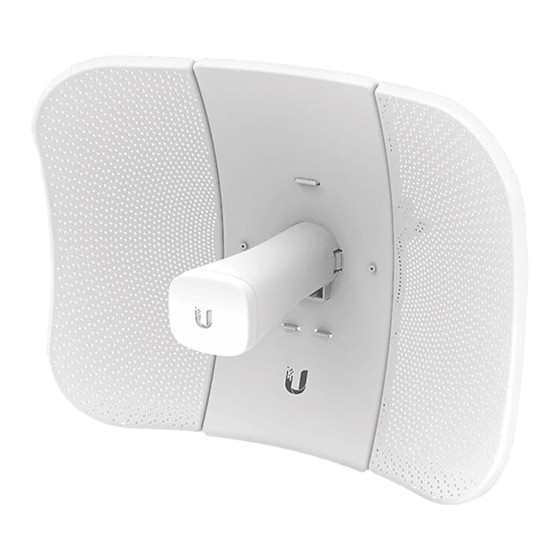
Ubiquiti LiteBeam LBE-5AC-Gen2 Quick Start Manual
Hide thumbs
Also See for LiteBeam LBE-5AC-Gen2:
- Quick start manual (5 pages) ,
- Quick start manual (33 pages) ,
- Quick start manual (29 pages)
Advertisement
Hardware Installation
The LiteBeam AC was designed for outdoor use and quick
mounting on a pole.
1. Assemble the antenna reflector by attaching the
Side Reflector Panels to the Center Reflector Panel:
a. Insert the heads of the two mounting studs on the
Center Reflector Panel into the large opening of the
slotted holes of the Side Reflector Panel.
b. Slide the Side Reflector Panel down until the top edges
of the panels align. The Side Reflector Panel is captured
when both heads of the mounting studs are positioned
over the narrow opening of the slotted holes.
c. Repeat the assembly for the other Side Reflector Panel.
Advertisement
Table of Contents

Summary of Contents for Ubiquiti LiteBeam LBE-5AC-Gen2
- Page 1 Hardware Installation The LiteBeam AC was designed for outdoor use and quick mounting on a pole. 1. Assemble the antenna reflector by attaching the Side Reflector Panels to the Center Reflector Panel: a. Insert the heads of the two mounting studs on the Center Reflector Panel into the large opening of the slotted holes of the Side Reflector Panel.
- Page 2 2. Hold the reflector assembly by hand (do not use a tabletop or flat surface) and insert the Feed Receiver into the reflector assembly to secure the panels: a. Align the arrows on the Center Reflector Panel and the Feed Receiver, and insert both edges of the Side Reflector Panels and Center Reflector Panels into the Securing Arms of the Feed Receiver.
- Page 3 WARNING: Do not install the Feed Receiver into the reflector assembly by pushing down onto a tabletop or other flat surface as this can deform the panels. Hold the reflector assembly by hand. c. For additional support, there are eight machine screws that secure the Side Reflector Panels to the antenna assembly.
- Page 4 3. Insert the Antenna Feed into the Feed Receiver until the feed locks into place. 4. Turn the Port Cover counterclockwise to reveal the Ethernet Port on the Antenna Feed.


Need help?
Do you have a question about the LiteBeam LBE-5AC-Gen2 and is the answer not in the manual?
Questions and answers