Table of Contents
Advertisement
Quick Links
Advertisement
Table of Contents

Related Manuals for Ubiquiti airFiber 5


Summary of Contents for Ubiquiti airFiber 5
- Page 1 5 GHz Point to Point 1.0+ Gbps Radio Model: AF-5, AF-5U...
-
Page 3: Package Contents
Power Cord Quick Start Guide (Qty. 2) (50V, 1.2A) TERMS OF USE: Ubiquiti radio devices must be professionally installed. Shielded Ethernet cable and ™ earth grounding must be used as conditions of product warranty. TOUGHCable is designed for outdoor installations. It is the customer’s responsibility to follow local country regulations, including operation within legal frequency channels, output power, and Dynamic Frequency Selection (DFS) requirements. -
Page 4: Hardware Overview
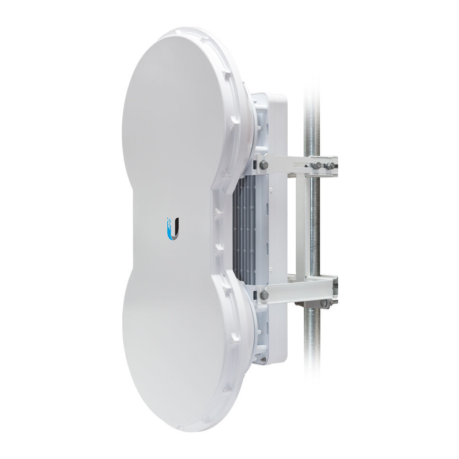
airFiber® AF-5/AF-5U Quick Start Guide Hardware Overview Side Lanyard Attachment Loop Elevation Rod Hex Nut to adjust Elevation Rod Pre-Installed M10 x25 Flanged Bolts Grounding Point Lanyard Attachment Loop Assembled View... - Page 5 Hardware Overview Interfaces OVERLOAD MASTER LINK REMOTE RESET 4X TO 0.25X LOCAL MANAGEMENT DATA SPEED SPEED Interface Description To reset to factory defaults, press and hold the Reset Button Reset button for more than five seconds while the unit is already powered on. Displays the received signal strength in dBm of Remote Display the remote airFiber radio.
- Page 6 airFiber® AF-5/AF-5U Quick Start Guide LEDs OVERLOAD MASTER LINK REMOTE RESET 4X to 0.25X LOCAL DATA MANAGEMENT SPEED SPEED State Status No GPS Synchronization Operational (Strong Signal) Normal Flash* Non-Operational (Weak Signal) Slave mode Master Master mode RF Off Short Flash* Syncing Link Normal Flash*...
- Page 7 Hardware Overview State Status Displays the received signal Local strength in dBm of the local airFiber radio. Overload Fast Flash Overload Condition (Unlabeled) 10x (1024QAM MIMO) 256QAM MIMO 64QAM MIMO 16QAM MIMO Long Flash* QPSK MIMO 4x to 0.25x Normal Flash* 1x QPSK xRT ™...
-
Page 8: Other Requirements
airFiber® AF-5/AF-5U Quick Start Guide Installation Requirements Pre-Assembly Tool • 13 mm wrench Pole-Mounting Tool • 17 mm wrench Other Requirements • Clear line of sight between airFiber radios • Clear view of the sky for proper GPS operation • Vertical mounting orientation •... -
Page 9: Installation Overview
Installation Overview Installation Overview We recommend that you configure your paired airFiber radios before mounting. Below is an overview of the installation with specific details in the following instructions: • Connect Power over Ethernet to the Data port, and connect an Ethernet cable between your computer and the Management port. - Page 10 airFiber® AF-5/AF-5U Quick Start Guide 2. Connect an Ethernet cable to the Data port. OVERLOAD MASTER LINK REMOTE RESET 4X to 0.25X LOCAL MANAGEMENT DATA SPEED SPEED 3. Connect the other end of the Ethernet cable from the Data port to the Ethernet port labeled POE on the GigE PoE Adapter. 4.
-
Page 11: Airfiber Configuration
airFiber Configuration airFiber Configuration The instructions in this section explain how to access the airFiber Configuration Interface and configure the following settings: Configure one airFiber radio as the Master and • Wireless Mode the other as the Slave. • Duplex The airFiber radio supports both half-duplex and full-duplex operation. - Page 12 airFiber® AF-5/AF-5U Quick Start Guide 1. Connect an Ethernet cable from your computer to the Management port on the airFiber radio. OVERLOAD MASTER LINK REMOTE RESET 4X to 0.25X LOCAL MANAGEMENT DATA SPEED SPEED 2. Configure the Ethernet adapter on your computer with a static IP address on the 192.168.1.x subnet.
- Page 13 airFiber Configuration 5. The Main tab will appear. Click the Tools drop-down and select Link Calculator. This tool will guide you on how to best minimize bandwidth and power/interference issues. If you do not see the Link Calculator, then upgrade Note: the firmware on your airFiber radios.
- Page 14 airFiber® AF-5/AF-5U Quick Start Guide 9. Configure the Wireless Security: a. Select the AES Key Type, HEX or ASCII. b. For the Key field: Enter 16 bytes (eight, 16-bit HEX values: 0-9, A-F, or a-f ). You can omit zeroes and use colons, similar to the IPv6 format.
-
Page 15: Hardware Installation
Hardware Installation Hardware Installation The mounting hardware of the airFiber radio can be pre-assembled before pole-mounting. Mounting Hardware Pre-Assembly 1. Insert two M10x150 Carriage Bolts into the Lower Mount Bracket. 2. Insert two M10x150 Carriage Bolts into the Upper Mount Bracket with Elevation Rod. - Page 16 airFiber® AF-5/AF-5U Quick Start Guide 3. Attach the Lower Mount Bracket to the I-Bracket using two Serrated Flange Bolts. Ensure that the slots face up and securely tighten the bolts. Proper slot orientation...
- Page 17 Hardware Installation 4. Attach the Upper Mount Bracket with Elevation Rod to the I-Bracket using two Serrated Flange Bolts. Ensure that the orientation of the Upper Mount Note: Bracket matches the illustration below, with the Elevation Rod on the correct side.
- Page 18 airFiber® AF-5/AF-5U Quick Start Guide 5. Attach the Pole Clamps to the Mount Brackets. a. Slide the slotted hole of each Pole Clamp over one upper and one lower M10x150 Carriage Bolt. b. Place one Serrated Flange Nut on each M10x150 Carriage Bolt.
- Page 19 Hardware Installation 6. Attach the Azimuth Support Brackets together. a. Insert the two M10x100 Carriage Bolts into the Azimuth Support Bracket that has two slotted holes. b. Slide the slotted hole of the other Azimuth Support Bracket over one M10x100 Carriage Bolt. c.
-
Page 20: Pole Mounting
airFiber® AF-5/AF-5U Quick Start Guide Pole-Mounting 1. Attach the Azimuth Support Brackets to the pole just beneath the area where the airFiber radio will be attached. Note: The mounting assembly can accommodate a Ø 38.1 - 101.6 mm (1.5" - 4.0") pole. a. - Page 21 Hardware Installation 2. Attach the mounting assembly to a pole. a. Orient the mounting assembly around the pole so it is aimed in the direction of the other airFiber radio. b. Slide the open slot of each Pole Clamp over the corresponding M10x150 Carriage Bolt.
- Page 22 airFiber® AF-5/AF-5U Quick Start Guide 3. Lift the airFiber radio and align the two lower Pre-Installed M10x25 Flanged Bolts with the slots on the Lower Mount Bracket. Seat the bolts in the slots.
- Page 23 Hardware Installation 4. Align the two upper Pre-Installed M10x25 Flanged Bolts of the airFiber radio next to the slots on the Upper Mount Bracket. Lift the airFiber radio and seat the bolts in the slots.
- Page 24 airFiber® AF-5/AF-5U Quick Start Guide 5. Attach a ground wire: a. Remove the nut from the Grounding Point. b. Attach a ground wire (min. 8 AWG or 10 mm ) to the lug and replace the nut to secure the wire. c.
-
Page 25: Connecting Ethernet
Connecting Ethernet Connecting Ethernet 1. Push the button and slide the port cover down to access the cable ports. (The port cover cannot be completely removed.) 2. Connect the Data/PoE Ethernet cable: a. Feed an outdoor, shielded CAT6 cable up through the rightmost cable feed slot on the bottom of the port cover. - Page 26 airFiber® AF-5/AF-5U Quick Start Guide 3. Connect the other end of the Ethernet cable from the Data port to the Ethernet port labeled POE on the GigE PoE Adapter. 4. Connect an Ethernet cable from your network to the Ethernet port labeled LAN on the GigE PoE Adapter.
- Page 27 Connecting Ethernet Below is a diagram of a finished installation with recommended surge protectors installed. Ground to Pole, Tower, or Grounding Block: Max. 1 m from Ground Bonding Point Outdoor GigE PoE Surge Protector Outdoor GigE PoE Surge Protector GigE PoE Adapter Power Source...
- Page 28 airFiber® AF-5/AF-5U Quick Start Guide Alignment Tips • To accurately align the airFiber radios for best performance, you MUST align only one end of the link at a time. • For more convenient alignment, you may consider using long-range scopes (not included) temporarily attached to your airFiber radios.
-
Page 29: Establishing A Link
Alignment Establishing a Link Adjust the positions of the Master and the Slave to establish a link. The Master must be aimed first at the Slave because Note: the Slave does not transmit any RF signal until it detects transmissions from the Master. 1. - Page 30 airFiber® AF-5/AF-5U Quick Start Guide Visually aim the Master at the Slave. To adjust the Master Master's position: a. Rotate the airFiber radio on the pole to align the azimuth. b. Use the hex nut on the Elevation Rod to adjust the elevation. Note: Do NOT make simultaneous adjustments on the Master and Slave.
- Page 31 Alignment Aim the Slave at the Master to achieve the strongest Slave signal level on the Remote LED Display of the Slave. Values on the LED Displays are displayed in Note: negative (-) dBm. For example, 67 represents a received signal level of -67 dBm.
-
Page 32: Installer Compliance Responsibility
airFiber® AF-5/AF-5U Quick Start Guide There are three methods for determining the received signal level: • LED Displays (described above) • airFiber Configuration Interface (webpage) • Audio tone (optional equipment required) Refer to the airFiber AF-5/AF-5U User Guide for instructions on the airFiber Configuration Interface and audio tone methods. - Page 33 © 2013-2015 Ubiquiti Networks, Inc. All rights reserved. Ubiquiti, Ubiquiti Networks, the Ubiquiti U logo, the Ubiquiti beam logo, airFiber, TOUGHCable, and xRT are trademarks or registered trademarks of Ubiquiti Networks, Inc. in the United States and in other countries. All other trademarks are the property of their respective owners.
Need help?
Do you have a question about the airFiber 5 and is the answer not in the manual?
Questions and answers