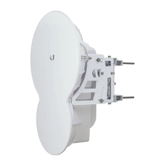
Ubiquiti AF24 Quick Start Manual
24 ghz point to point
1.4+ gbps radio
Hide thumbs
Also See for AF24:
- User manual (50 pages) ,
- Quick start manual (37 pages) ,
- Quick start manual (41 pages)
Table of Contents
Advertisement
Quick Links
Advertisement
Table of Contents

Related Manuals for Ubiquiti AF24


Summary of Contents for Ubiquiti AF24
- Page 1 24 GHz Point to Point 1.4+ Gbps Radio Model: AF24...
-
Page 3: Package Contents
Thank you for purchasing the airFiber 24 GHz Point-to-Point ™ Radio, model AF24. This Quick Start Guide is designed to guide you through the installation of the airFiber AF24 and show you how to access the airFiber Configuration Interface. Package Contents... -
Page 4: Hardware Overview
airFiber 24G Quick Start Guide Hardware Overview Side Lock Bolts Alignment Bracket Elevation Adjustment Azimuth Adjustment Lock Bolts Ground Bonding Point... - Page 5 Hardware Overview Back Lock Bolts Lock Bolts Elevation Adjustment Azimuth Adjustment Lock Bolts Lock Bolts Port Cover...
- Page 6 airFiber 24G Quick Start Guide Interfaces RESET DATA LED Display CONFIG Interface Description To reset to factory defaults, press and hold the RESET RESET button for more than five seconds while the unit is already powered on. DATA 10/100/1000 Mbps port handles all user traffic. Port for audio tone aiming.
- Page 7 Hardware Overview State Status 10/100 Mbps Speed 1000 Mbps No Ethernet Link Link/Act Ethernet Link Established Random Flashing Ethernet Activity No GPS Synchronization Operational (Strong Signal) Normal Flash* Operational (Weak Signal) 1x (QPSK SISO) Short Flash* 2x (QPSK MIMO) Modulation Normal Flash* 4x (16QAM MIMO) Long Flash*...
-
Page 8: Installation Requirements
airFiber 24G Quick Start Guide Installation Requirements • 17 mm wrench • 13 mm socket wrench or driver • Clear line of sight between airFiber radios • Clear view of the sky for proper GPS operation • Mounting location with < 0.5° displacement due to twist and sway under wind loading • Mounting point: • At least 1 meter below the highest point on the structure... -
Page 9: Connecting Power Over Ethernet
Connecting Power over Ethernet • Reconnect at the site. • After you have mounted the airFiber radios, establish and optimize the RF link. Connecting Power over Ethernet 1. Press down on the indicator arrows and slide the Port Cover off. 2. - Page 10 airFiber 24G Quick Start Guide 3. Connect the other end of the Ethernet cable from the DATA port to the Ethernet port labeled POE on the PoE Adapter. 4. Connect the Power Cord to the power port on the PoE Adapter. Connect the other end of the Power Cord to a power source.
-
Page 11: Airfiber Configuration
The instructions in this section explain how to access the airFiber Configuration Interface and configure the following settings: • Wireless Mode Configure one airFiber AF24 as the Master and the other as the Slave. • Duplex The airFiber AF24 supports both half-duplex and full-duplex operation. - Page 12 24G Quick Start Guide 1. Connect an Ethernet cable from your computer to the CONFIG port on the airFiber AF24. 2. Configure the Ethernet adapter on your computer with a static IP address on the 192.168.1.x subnet (for example, 192.168.1.100).
- Page 13 Configuration 5. Click the Wireless tab. 6. Enter the Basic Wireless Settings: a. For one airFiber AF24, select Master from the Wireless Mode drop-down. For the other airFiber AF24, keep the default, Slave. b. Enter a name in the Link Name field. This should be the same on both the Master and the Slave.
- Page 14 airFiber 24G Quick Start Guide 7. Configure the Wireless Security: a. Select the AES Key Type, HEX or ASCII. b. For the Key field: Enter 16 bytes (eight, 16-bit HEX values: 0-9, A-F, or a-f ). You can omit zeroes and use colons, similar to the IPv6 format.
-
Page 15: Hardware Installation
2. Attach the Pole Mount Bracket to a pole. a. Orient the Pole Mount Bracket around the pole so it is aimed in the direction of the other airFiber AF24. b. Insert the M10x150 Carriage Bolts into the Pole Clamps. - Page 16 airFiber 24G Quick Start Guide 3. Loosen, but do NOT remove the eight Lock Bolts located on the Alignment Bracket. 4. Ensure that there is a 6 mm gap between the head of each M8x14 Serrated Flange Screw and the Alignment Bracket. 6 mm...
- Page 17 Hardware Installation 5. Lift the airFiber AF24 and align the four M8x14 Serrated Flange Screws with the slots on the Pole Mount Bracket. Seat the screws in the slots. Securely tighten the screws. WARNING: To prevent injury, ensure that all four screws...
- Page 18 airFiber 24G Quick Start Guide 6. Attach a ground wire by performing the following steps: a. Remove the nut from the Ground Bonding Point. b. Attach a ground wire (min. 8 AWG or 10 mm ) to the lug and replace the nut to secure the wire.
-
Page 19: Connecting Ethernet
Connecting Ethernet Connecting Ethernet 1. Press down on the indicator arrows and slide the Port Cover off. 2. Connect a TOUGHCable or other outdoor, shielded CAT5e/6 cable to the DATA port. 3. Create a strain relief for the Ethernet cable by feeding a cable tie through the tie slot under the cable. - Page 20 airFiber 24G Quick Start Guide 4. Connect the other end of the Ethernet cable from the DATA port to the Ethernet port labeled POE on the PoE Adapter. 5. Connect an Ethernet cable from your network to the Ethernet port labeled LAN on the PoE Adapter. 6.
- Page 21 Connecting Ethernet Below is a diagram of a finished installation with recommended surge protectors installed. Ground to Pole, Tower, or Grounding Block (Max. 1 m from Ground Bonding Point) Max. 1 m Outdoor GigE PoE Surge Protector GigE Router or Switch Outdoor GigE PoE Surge Protector GigE PoE Adapter...
- Page 22 airFiber 24G Quick Start Guide Alignment Tips • We recommend using a pair of installers in constant communication because in the fine-tuning stage, one installer makes azimuth and elevation adjustments on one airFiber radio while the other installer reports the received signal level at the other airFiber radio.
- Page 23 Alignment Master Ensure the Azimuth (AZ) and Elevation (EL) Adjustment Bolts are in the middle of their adjustment ranges. Elevation (EL) Adjustment Bolt Azimuth (AZ) Adjustment Bolt Master Aim the Master at the Slave. If necessary, adjust the Master's position on the pole: a.
- Page 24 airFiber 24G Quick Start Guide Slave Ensure the Azimuth (AZ) and Elevation (EL) Adjustment Bolts are in the middle of their adjustment ranges. Elevation (EL) Adjustment Bolt Azimuth (AZ) Adjustment Bolt Slave Aim the Slave at the Master to achieve the strongest received signal level on the Slave's numeric LED Display, which is located next to the CONFIG port.
- Page 25 Sweep the Elevation (EL) Adjustment Bolt of the Master through its adjustment range. Master Elevation (EL) Adjustment Bolt Master RF Power (-dBm) Note: If the LED Display indicates an overload condition , refer to the airFiber AF24 User Guide at: documentation.ubnt.com for more information.
- Page 26 airFiber 24G Quick Start Guide Fine-Tuning the Link The Azimuth (AZ) and Elevation (EL) Adjustment Bolts of the Alignment Bracket adjust the azimuth and elevation within a range of ±10°. For accurate alignment, make adjustments on one end of the link while the other installer reports the received signal level at the other end of the link.
- Page 27 4. Lock the alignment on both airFiber radios by tightening all eight Lock Bolts on the Alignment Bracket. Observe the LED Display on each airFiber AF24 to ensure that the value remains constant while tightening the Lock Bolts. If the LED...
-
Page 28: Installer Compliance Responsibility
airFiber 24G Quick Start Guide Installer Compliance Responsibility Devices must be professionally installed and it is the professional installer's responsibility to make sure the device is operated within local country regulatory requirements. The Frequencies and Output Power fields are provided to the professional installer to assist in meeting regulatory requirements. -
Page 29: Specifications
Specifications Specifications airFiber AF24 Dimensions 649 x 426 x 303 mm Weight 10.5 kg (Mount Included) Operating Frequency 24.05 – 24.25 GHz Max Power Consumption < 50 W Power Supply 50V, 1.2A PoE GigE Adapter (Included) Power Method Passive Power over Ethernet (42-58V) -
Page 30: Electrical Safety Information
airFiber 24G Quick Start Guide Electrical Safety Information 1. Compliance is required with respect to voltage, frequency, and current requirements indicated on the manufacturer’s label. Connection to a different power source than those specified may result in improper operation, damage to the equipment or pose a fire hazard if the limitations are not followed. -
Page 31: Warranty Conditions
Compliance No Products will be accepted for replacement or repair without obtaining a Return Materials Authorization (RMA) number from UBIQUITI NETWORKS. Products returned without an RMA number will not be processed and will be returned to Buyer freight collect. UBIQUITI NETWORKS shall have no obligation to make repairs or replacement necessitated by catastrophe, fault, negligence, misuse, abuse, or accident by Buyer, Buyer’s customers or any other parties. -
Page 32: Rf Exposure Warning
airFiber 24G Quick Start Guide NOTE: This equipment has been tested and found to comply with the limits for a Class A digital device, pursuant to part 15 of the FCC Rules. These limits are designed to provide reasonable protection against harmful interference when the equipment is operated in a commercial environment. -
Page 33: Declaration Of Conformity
Declaration of Conformity Les antennes utilisées pour ce transmetteur doivent être installé en considérant une distance de séparation de toute personnes d'au moins 107 cm et ne doivent pas être localisé ou utilisé en conflit avec tout autre antenne ou transmetteur, excluant la liste de certification de ce produit. CE Marking CE marking on this product represents the product is in compliance with all directives that are applicable to it. - Page 34 airFiber 24G Quick Start Guide Ελληνική ΜΕ ΤΗΝ ΠΑΡΟΥΣΑ UBIQUITI NETWORKS ΔΗΛΩΝΕΙ ΟΤΙ UBIQUITI NETWORKS device, ΣΥΜΜΟΡΦΩΝΕΤΑΙ ΠΡΟΣ ΤΙΣ ΟΥΣΙΩΔΕΙΣ [Greek] ΑΠΑΙΤΗΣΕΙΣ ΚΑΙ ΤΙΣ ΛΟΙΠΕΣ ΣΧΕΤΙΚΕΣ ΔΙΑΤΑΞΕΙΣ ΤΗΣ ΟΔΗΓΙΑΣ 1995/5/ΕΚ. Magyar Alulírott, UBIQUITI NETWORKS nyilatkozom, hogy a UBIQUITI NETWORKS device, megfelel a vonatkozó alapvetõ [Hungarian] követelményeknek és az 1999/5/EC irányelv egyéb elõírásainak.
-
Page 36: Ubiquiti Networks Support
Ubiquiti Networks Support Email: support@ubnt.com Phone (9 a.m. - 5 p.m. PST): 408-942-1153 Online Resources Wiki Page: wiki.ubnt.com Support Forum: forum.ubnt.com Downloads: downloads.ubnt.com w w w . u b n t . c o m © 2012 Ubiquiti Networks, Inc. All rights reserved.
Need help?
Do you have a question about the AF24 and is the answer not in the manual?
Questions and answers