Table of Contents
Advertisement
Quick Links
Instruction Manual
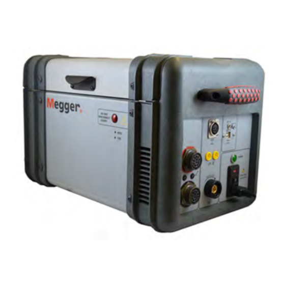
Three-Phase Ratio & Winding Resistance
Transformer Test Set
MWA3XX Series
Catalog Numbers. MWA300, MWA300-47,
MWA330A, MWA330A-47
HIGH-VOLTAGE EQUIPMENT
Read this entire manual before operating equipment
for
Valley Forge Corporate Center
2621 Van Buren Avenue
Norristown, PA 19403-2329
U.S.A.
610-676-8500
www.megger.com
MWA300_330A-UG-EN-V05
May 2017
Advertisement
Table of Contents
Troubleshooting

Subscribe to Our Youtube Channel
Related Manuals for Megger MWA3 Series


Summary of Contents for Megger MWA3 Series
- Page 1 Instruction Manual Three-Phase Ratio & Winding Resistance Transformer Test Set MWA3XX Series Catalog Numbers. MWA300, MWA300-47, MWA330A, MWA330A-47 HIGH-VOLTAGE EQUIPMENT Read this entire manual before operating equipment Valley Forge Corporate Center 2621 Van Buren Avenue Norristown, PA 19403-2329 U.S.A. 610-676-8500 www.megger.com...
- Page 3 Three-Phase Ratio & Winding Resistance Transformer Test Set MWA3XX Series...
- Page 4 Specifications are subject to change without notice. WARRANTY Products supplied by Megger are warranted against defects in material and workmanship for a period of one year following shipment. Our liability is specifically limited to replacing or repairing, at our option, defective equipment.
-
Page 5: Table Of Contents
Table of Contents 1 MWA300 PRODUCT OVERVIEW ........................ 1 2 SAFETY ................................5 3 SPECIFICATIONS ............................. 7 Electrical ................................... 7 Input Power ..............................7 Protective Devices (Fuses) ..........................7 Ratio Specifications ..............................8 ... - Page 6 Resistance Test Screen ............................31 Basic Connections to MWA300/330A ......................32 6 TRANSFORMER TESTING APPLICATIONS – RATIO & WINDING ......... 33 Single-Phase, Two-Winding Transformers – including Typical Pole Type transformers with Dual Secondary’s ................................34 Three-Phase, Two-Winding Transformers ....................... 37 ...
- Page 7 LIST OF FIGURES Figure 1-1 Top Panel Controls ..........................2 Figure 6-1 Setup for Testing Single-Phase Transformer (Vector Diagram 1P0) ........34 .. Figure 6-2 Setup for Testing Single-Phase Autotransformer (Vector Diagram 1P0) ......34 .. Figure 6-3 Setup for Testing Single-Phase, Type A (Straight Design) Step Voltage Regulator ...
- Page 8 Prior to operation, check for loosened hardware or damage incurred during transit. If these conditions are found, a safety hazard is likely, DO NOT attempt to operate equipment. Please contact Megger as soon as possible. MWA300 Transformer Ratio & Winding Resistance Test Set...
-
Page 9: Mwa300 Product Overview
MWA300 PRODUCT OVERVIEW The MWA300/330A test set is an automatic unit which is designed to be controlled via a computer running PowerDB Lite software. The MWA330A includes a built-in 12 inch controller which is used in place of a PC. The test set measures the turns ratio, phase shift, excitation current and winding resistance of power, distribution, and instrument transformers. - Page 10 Top Panel Controls Figure 1-1 Top Panel Controls 1. Power Input Receptacle: ON/OFF switch, and Mains fuse holder. ON/OFF power switch and input power receptacle provides power to the test set. 2. H – Cable Receptacle: Plug receptacle for connecting test leads to the high- voltage (H) winding of a transformer 3.
- Page 11 3. USB Port: Used for various functions including external memory and external mouse/keyboard control. 4. Rear USB Port Hub: Used for external Megger instrument control such as Delta4000, S1/MIT Insulation test set, MLR10. 5. Rear Ethernet Port: Used for external Megger instrument control –...
- Page 12 MWA300_330A-UG-EN-V05 May 2017...
-
Page 13: Safety
In the event of equipment malfunction, the unit should immediately be de-energized and returned to Megger for repair. The Safety precautions, herein, are not intended to replace your Company’s Safety Procedures. Refer to IEEE 510 - 1983, IEEE Recommended Practices for Safety in High-Voltage and High-Power Testing, for additional information. - Page 14 Personnel using heart pacemakers should obtain expert advice on the possible risks before operating this equipment or being close to the equipment during operation. Input Power Precautions This instrument operates from a single-phase, sine wave, power source. It has a three-wire power cord and requires a two-pole, three-terminal (live, neutral, and ground) type input source.
-
Page 15: Specifications
SPECIFICATIONS Electrical Input Power Cat. No. 108-132V, 60 Hz, ±2 Hz, 660 VA MWA300/330A: (207-253V with fuse change to 4.0 amp*) IEC 1010-1 installation category II *Calibration of phase may differ if nominal line frequency changes. Cat. No. 207-253V, 50 Hz, ±2 Hz, 660 VA MWA300/330A-47: (108-132V with fuse change to 6.3 amp*) IEC 1010-1 installation category II... -
Page 16: Ratio Specifications
RATIO SPECIFICATIONS Output AC Test Voltage and Current Test Voltages: 80V rms, 40V rms, 8V rms Current: up to 500 ma Test Frequency Same as line frequency Loading of Test Transformer Less than 0.2 VA Measuring Ranges Turns Ratio: 80V ac: 0.8 to 45,000, 5 digit resolution 40V ac: 0.8 to 25,000, 5 digit resolution 8V ac: 0.8 to 8,000, 5 digit resolution Excitation Current:... -
Page 17: Measurement Method
Specifications Measurement Method In accordance with ANSI/IEEE C57.12.90-2013 and IEC 60076-1 Transformer Winding Phase Relationship ANSI C57.12.70-2011 CEI/IEC 76-1:2011, IEC 60076-1 and CIGRE TB 445 AS-2374, Part 4-2003 (Australian Standard) Measuring Time 8 to 37 seconds depending on mode of operation and type of transformer Winding Resistance Specifications DC Output Current (User Selectable Ranges) 10 mA... -
Page 18: Resistance Ranges
Resistance Ranges Current Range (A) Resistance Range (Ω) Resolution ((Ω) 10 µΩ to 0.2 Ω 10 A 0.000001 0.2 Ω to 2 Ω 10 A 0.0001 100 µΩ to 2 Ω 0.00001 2 Ω to 20 Ω 0.001 1 mΩ to 20 Ω 100 mA 0.0001 20 Ω... -
Page 19: Environmental Conditions
Specifications Environmental Conditions 14° to 122°F (-10 to 50 °C) Operating Temperature Range: -22° to 158°F (-30 to 70 °C) Storage Temperature Range: Relative Humidity: 0 to 90% noncondensing Physical Data Dimensions: Instrument: 11.5 H x 11.5 W x 18 D in. (290H x 290 W x 460D mm) Weight: MWA300 with standard provided accessories:... - Page 20 MWA300_330A-UG-EN-V05 May 2017...
-
Page 21: Software Installation
PowerDB Lite PC version. No difference in operation exists, except where upgrades between the PC and the MWA330A are not maintained. Upgrading the MWA330A is different than upgrading a PC. Please refer to Megger website similar to: http://us.megger.com/my-account/software-downloads/for latest 'On Board' download software and instructions. -
Page 22: Software Installation (Pc Portion Only)
PowerDB Lite version available. NOTE: For MWA330A, software version is available on our www.megger.com website located under “Software Support” and requires a user login. It will load onto the MWA330A via the USB memory port on the controller portion. -
Page 23: General Testing Procedures
Software Installation 3. Select Default Settings (Language and Units of Measure). 4. Install Shield Wizard will complete the installation of PowerDB Lite. Click Finish to close the installation program. General Testing Procedures Getting Started 1. To determine that the MWA hardware is operational, observe the following: Once all safety precautions are taken, and all circuit connections are made, the user may safely turn the ON/OFF switch to the ON position and operate the test instrument as described herein. - Page 24 3. Select MWA from the Instrument Setup screen. It may be located in 'Favorites' or 'Transformer/Power Factor Test Sets' and can be relocated as desired. The MWA300 uses USB connection only. Once MWA is selected, the proper settings for USB are pre-selected, and no further changes should be required. PLEASE ALLOW SUFFICIENT TIME FOR DRIVERS TO LOAD WHEN CONNECTING TO MWA300 FOR THE FIRST TIME.
- Page 25 IF THE ABOVE DOES NOT RESOLVE ISSUES, PLEASE REFER TO SECTION 8 OF THIS MANUAL FOR TROUBLE SHOOTING/REINSTALLATION OF DRIVERS. Beyond this, please contact your local ASC or direct to VFsupport@megger.com. MWA300_330A-UG-EN-V05 May 2017...
- Page 26 MWA300_330A-UG-EN-V05 May 2017...
-
Page 27: Three-Phase Ttr & Winding Resistance Testing
THREE-PHASE TTR & WINDING RESISTANCE TESTING The following is a detailed description of operational aspects of MWA test forms, with 3Ɵ Turns & Winding Resistance form below used as a reference. All other MWA forms use common methods as described in the example below. Ɵ... -
Page 28: Test Form Controls - General
Test Form Controls - General Once a form is opened, all forms have a set of standard controls which are available across the top of the form as shown below. This allows common functions such as saving, deleting, opening results, together with functions as described below. New: Allows a different test form to be selected within the MWA - brings up selection list from menu in Item 1 above. -
Page 29: Form Settings
Three Phase TTR& Winding Resistance Testing Form Settings Diagram Number: Relates to TTR/MTO function where each vector combination has a specific diagram number associated with it. ii. Standard: ANSI/IEC/AUS depending on national standard used. iii. Phase Display: When testing ratio, accompanying phase result displayed as 'Degrees or Minutes' (60 Minutes = 1 Degree). -
Page 30: Tap Settings
Tap Settings Override Calc. Voltages/Tap Labels: Allows individual entry for each field. Typically used for custom transformers. NOTE: When checked, all fields in tables below remain empty until manually populated. ii. H and L Numbering: Allows labeling to follow transformer nameplate convention. -
Page 31: Resistance/Ratio Settings
Three Phase TTR& Winding Resistance Testing Resistance/Ratio Settings Nameplate Recommended: DC Test Current is provided as a guide for test current limits for each winding. NOTE: For high ratio transformers, testing windings in series may not give timely or accurate results because of insufficient test current for secondary windings. -
Page 32: Transformer Nameplate
Transformer Nameplate Vector Selection: Once form setting (above) selects proper standard, one depresses the vector and a 'pop up' Vector Selector will appear, or 'right click' to select primary and secondary vector until it matches Transformer Nameplate. ii. Transformer Nameplate Voltages: Line-to-line only, in volts. iii. -
Page 33: Transformer Test Conditions
Three Phase TTR& Winding Resistance Testing Transformer Test Conditions Environmental (Weather) Test Conditions: Input. ii. Oil/Winding Temperature: Readings input from transformer temperature gauges and used for optional correction of results to normalized temperatures. iii. Test Status: Once testing is complete, indicates condition of the asset under test. -
Page 34: Ratio Test
Ratio Test Test Setup: Reflects input from Transformer Nameplate (5.) above and tap under test. ii. Test Results for each phase. iii. Retest A/B/C: Depressing will retest individual phase. iv. Retest or Test Tap or Done: Retest a tap, terminates test, or allows continuation to test next tap. -
Page 35: Winding Resistance Testing
Three Phase TTR& Winding Resistance Testing Winding Resistance Testing Descriptions for the following testing methods described below involve 3 methods of performing testing. 1. An automated sequence is determined and test operates through each winding and tap as required – 2. -
Page 36: Method 1 - Resistance Test Wizard
Method 1 - Resistance Test Wizard - Resistance Test Wizard is designed to automate the winding resistance test, allowing the Transformer Nameplate Input above is combined with operator selection of taps to complete a test sequence with minimal button presses. This wizard also allows testing of OLTC taps without discharge of test current during transition (between) of taps, making testing both more efficient (less time charging and discharging winding and less button pressing) as well as diagnostic by indication of a... -
Page 37: Method 2 - Measuring Tap - All Phases Winding Resistance
Three Phase TTR& Winding Resistance Testing Method 2 – Measuring Tap – All Phases Winding Resistance - Test #: Depressing this button commences testing for a specific tap row (circled). Testing is conducted sequentially (up to 2 windings at once), ensuring optimization of magnetized core. -
Page 38: Method 3 - Measuring Individual Tap Winding
Method 3 – Measuring Individual Tap Winding To begin testing an individual winding, simply depress using (right click) the Reading or Space which requires testing. This will begin the test, applying the conditions previously set (% Stability, Test Current etc.). NOTE: Test Method 3 cannot validate 'Make Before Break' operation of OLTC tap changers because test current is discharged between each test. -
Page 39: Resistance Test Screen
Three Phase TTR& Winding Resistance Testing Resistance Test Screen Once a test sequence begins from Method 1-3 above, the following screen will appear: Test Setup: Allows changes to test parameters, which can be seen in Item iv above (and described in Item iv below). This button is 'greyed out' once testing begins or MTO instrument connection is not established. -
Page 40: Basic Connections To Mwa300/330A
Basic Connections to MWA300/330A Connections should be made in the order as listed below. Ground: Use the Megger supplied Safety Ground Cable 15 ft (4.6 m) to connect the MWA300 Ground Lug Terminal directly to Local Station Earth ground. Input Power Source Ground: Input Power Source Ground Terminal should be less than 0.1 Ω... -
Page 41: Transformer Testing Applications - Ratio & Winding
TRANSFORMER TESTING APPLICATIONS – RATIO & WINDING The setup and connection instructions included in Section 6, herein, pertaining to ratio, polarity, phase relation and winding resistance, assume that the transformer under test, connections, and terminal markings comply with the requirements of ANSI C57.12.70-2011 American National Standards Terminal Markings and Connections for Distribution and Power Transformers or IEC 60076-1 Test Procedures for Power Transformers. -
Page 42: Single-Phase, Two-Winding Transformers -Including Typical Pole Type Transformers With Dual Secondary's
Single-Phase, Two-Winding Transformers –including Typical Pole Type transformers with Dual Secondary’s Perform the following setup procedure for single-phase, two-winding transformers. 1. Connect the heavy-duty clamps marked H1(1U) and H2(1V) & X1(2U) & X2 (2V) of the test lead to the corresponding (high-voltage and low-voltage windings) terminals of the transformer under test. - Page 43 Transformer Testing Applications– Ratio & Winding To test windings other than H1(1U) – H2 (1V) and X1(2U) – X2 (2V), ensure that the heavy-duty clamp marked H1(U1) is connected to the lower numbered terminal and H2(V1) to the higher numbered terminal of the high-voltage winding. Similarly, X1(2U) and X2(2V) should be connected to the low-voltage winding.
- Page 44 Figure 6-4 Setup for Testing Single-Phase, Type B (Inverted Design) Step Voltage Regulator (Vector Diagram VREG) Figure 6-5 Showing connections to a Pole Type Transformer with 2 secondary windings. To test with PowerDB requires choice of 1P0, with 2 taps, changing leads between tests.
-
Page 45: Three-Phase, Two-Winding Transformers
Transformer Testing Applications– Ratio & Winding Three-Phase, Two-Winding Transformers Perform the following setup procedure for three-phase, two-winding transformers. 1. Connect the clamps marked H0(1N), H1(1U), H2(1V), and H3(1W) of the test lead to the corresponding (HV winding) terminals of the transformer under test. Refer to Table 6-2 for Test Lead Markings. - Page 46 Figure 6-6 Shows a Typical Connection to a 2 Winding YNyn or ZigZag – 8 Terminal Transformer Figure 6-7 Shows a Typical Connection to a Delta Delta or Yy (no neutral) 6 terminal transformer. NOTE: Neutral leads can be removed during this testing. MWA300_330A-UG-EN-V05 May 2017...
-
Page 47: Three-Phase, Three-Winding Transformers
Transformer Testing Applications– Ratio & Winding Three-Phase, Three-Winding Transformers This type of transformers has primary, secondary, and tertiary windings. Primary and secondary windings are tested as a regular three-phase, two-winding transformer. To test the tertiary winding, we connect to the primary and tertiary winding, and ignore the secondary winding during test procedure: As well, we can connect to the tertiary as a stand-alone winding: 1. -
Page 48: Unmounted Cts
CAUTION Never use AUTO mode of operation when testing the current transformers with the rated voltage below 80V ac. Most CTs can be tested with 8V ac excitation voltage. For larger CTs which have high saturation voltage (Relaying CTs fall into this category) higher test voltage results in better ratio and phase accuracy versus nameplate. - Page 49 Transformer Testing Applications– Ratio & Winding Figure 6-8 Setup for Testing Unmounted Current Transformer (only X1-X2 winding resistance can be tested for CTs) Use vector diagram 1P0 Figure 6-9 Setup for Testing Taps on Multiple Tap CT (only low side (X) windings can be tested for resistance) Use vector diagram 1P0.
-
Page 50: Bushing Current Transformer (Bct) Mounted On Single-Phase, Two-Winding Transformer
Bushing Current Transformer (BCT) Mounted on Single-Phase, Two-Winding Transformer A turn-ratio and winding resistance test can be performed on a BCT after it has been mounted on a circuit breaker or power transformer entrance bushing. The test can be performed without removal of the BCT from the equipment. Proceed as follows: 1. -
Page 51: Bushing Current Transformer (Bct) Mounted On Three-Phase Transformers
Transformer Testing Applications– Ratio & Winding Bushing Current Transformer (BCT) Mounted on Three-Phase Transformers A turn-ratio test can be performed on all three BCTs using a single setup. Figure 6- 11 shows the proper test connections when the BCTs are mounted on a typical delta winding and Figure 6-12 shows how when mounted on a typical wye winding. - Page 52 Figure 6-11 Setup for Testing BCT Mounted on Delta Winding on a Three-Phase Power Transformer (Shorting only required during Ratio Test) – Use diagram YNyn0 MWA300_330A-UG-EN-V05 May 2017...
- Page 53 Transformer Testing Applications– Ratio & Winding Figure 6-12 Setup for Testing BCT Mounted on Wye Winding of a Three-Phase Transformer (Shorting only required during ratio test) –Vector diagram YNyn0 MWA300_330A-UG-EN-V05 May 2017...
- Page 54 MWA300_330A-UG-EN-V05 May 2017...
-
Page 55: Test & Results Files - Saving And Retrieving
TEST & RESULTS FILES - SAVING AND RETRIEVING When testing, data management is a critical function required after testing. For efficiency, the ability to replicate testing within time intervals is important. The software provided, PowerDB, is able to meet most requirements for large and small companies. -
Page 56: Retrieving Results/Test Files
After initial results are saved with a file name as per above, all testing results continue to be saved as testing is conducted. In order to rename a test file (result) user has the option to save result under a different name, as a template or as a PDF (original test file remains unchanged). - Page 57 Test & Results Files - Saving and Retrieving Once MWA instrument is selected, user can open saved result to view results and/or to retest/append results, or use present form as a template (once settings are entered into form). MWA300_330A-UG-EN-V05 May 2017...
- Page 58 MWA300_330A-UG-EN-V05 May 2017...
-
Page 59: Service
(example NIST in the USA). As a result of this calibration procedure, each MWA test set may be NIST certified. To check the ratio portion calibration at a customer site or in the field, the Megger Calibration Standard Cat. No. 550055 or equivalent standard should be used. -
Page 60: Reason For Possible Inaccuracy In 1:1 Self-Test
NOTE: 1:1 Test Jig provided with all MWA3XX units To connect to this accessory, simply follow the connections from the Test Lead Markings matched to the Test Jig markings. Once all 3 phases are connected, choose any 3 phase form within the TTR, and select YNyn0 or Dd 0 from the vector selection tool on the test form. -
Page 61: Troubleshooting
Service Troubleshooting Resolving MWA Connection Issues (PC portion only) Connection to the MWA from a PC requires installation of software drivers from the original installation. If trouble is encountered in connecting to the MWA, the following steps can be followed to help resolve the issue. 1. - Page 62 6. Installing the missing drivers: AX88178 i. From the Explorer window, go to C:\Program Files (x86)\PowerDB Inc\PDB Optional Files\Sabrent USB-G1000 and open the appropriate file related to your Operating System folder (Windows 10 users = Windows_7_and_8). ii. Open the second folder (same name as previous folder). iii.
-
Page 63: Ratio Testing
Service USB Serial Port Go to C:\Program Files (x86)\PowerDB Inc\PDB Optional Files\CDM21218_Setup and open the appropriate dpinst-***.exe file based on your processor. Example below: Follow the instructions once driver begins installation. 7. After running the installers, the devices should install as previously shown in the Device Manager as seen above. - Page 64 operating conditions occur during transformer testing, error messages may appear (such as below) and may be accompanied by three short beeps. CHECK CONNECTIONS This message indicates that the transformer is not connected to the test set. The message may be caused by poor connection of one of the test leads, as well. PHASE A (or B, or C) EXCITATION CURRENT TOO HIGH This message indicates that excitation current exceeds 500 mA.
-
Page 65: The Ttr Troubleshooting Guide
Service The TTR Troubleshooting Guide Table 8-1 is arranged to help you evaluate the reasons for the TTR portion malfunction. The table lists possible test set malfunctions which may be encountered during operation and lists possible causes. Electronic circuit repairs should not be attempted in the field. -
Page 66: Repairs
Megger offers a complete Repair and Calibration Service (in Valley Forge, PA, USA) and recommends that its customers take advantage of this service for routine maintenance or in the event of any equipment malfunction. -
Page 67: Ordering Information / Spare Parts
PC 1:1 Test Jig (instrument self-test) 2005-249 OPTIONAL ACCESSORIES Universal lead sets, compatible with Megger MWA3XX Series products (up to 10 A DC max) 3-phase, 4-wire shielded test leads (H&X), complete with color coded universal Kelvin clamps 2008-30-KIT 3-Ø... - Page 68 ITEM CAT. NO. 36486-8 3-Ø 33 ft (10 m) Extension, H lead set 36486-9 3-Ø 33 ft (10 m) extension, H&X windings 2008-113-30 3-Ø Universal, 9 m (30 ft) H 2008-114-30 3–Ø Universal, 9 m (30 ft) X 2008-113-60 3–Ø Universal, 18 m (60 ft) H 2008-114-60 3-Ø...
Need help?
Do you have a question about the MWA3 Series and is the answer not in the manual?
Questions and answers