Table of Contents
Advertisement
AVTMMTO210
Rev 7
Sept 2013
Instruction Manual
for
Transformer Ohmmeter
DC Winding Resistance Test Set
MTO210
Catalog Number MTO210
HIGH-VOLTAGE EQUIPMENT
Read this entire manual before operating.
M
Valley Forge Corporate Center
2621 Van Buren Avenue
Norristown, PA 19403-2329
U.S.A.
610-676-8500
www.megger.com
Advertisement
Table of Contents

Related Manuals for Megger MTO210


Summary of Contents for Megger MTO210
- Page 1 AVTMMTO210 Rev 7 Sept 2013 Instruction Manual Transformer Ohmmeter DC Winding Resistance Test Set MTO210 Catalog Number MTO210 HIGH-VOLTAGE EQUIPMENT Read this entire manual before operating. Valley Forge Corporate Center 2621 Van Buren Avenue Norristown, PA 19403-2329 U.S.A. 610-676-8500 www.megger.com...
- Page 3 Transformer Ohmmeter DC Winding Resistance Test Set MTO210...
- Page 4 Specifications are subject to change without notice. WARRANTY Products supplied by Megger are warranted against defects in material and workmanship for a period of one year following shipment. Our liability is specifically limited to replacing or repairing, at our option, defective equipment.
-
Page 5: Table Of Contents
Table of Contents 1 Getting to know the MTO210 ........................... 1 Product Overview ..............................1 Top Panel Controls .............................. 3 2 Safety ..................................7 Safety is the responsibility of the user ....................... 7 General Safety Precautions ..........................8 ... - Page 6 List of Figures MTO210 Transformer Ohmmeter Test Set....................iii Figure 1: MTO210 Front Panel ........................3 Figure 2: Single Winding Measurement ......................26 Figure 3: Dual-Winding Test ........................... 28 Figure 4: Reading obtained is per phase, Resistance of A-N Winding ............. 31 Figure 5: Reading obtained is between pairs of terminals, Resistance of A and B Windings ....
-
Page 7: Mto210 Transformer Ohmmeter Test Set
Prior to operation, check for loosened hardware or damage incurred during transit. If these conditions are found, a safety hazard is likely, DO NOT attempt to operate equipment. Please contact Megger as soon as possible. MTO210 Transformer Ohmmeter Test Set... - Page 8 AVTMMTO210 Rev 7 Sept 2013...
-
Page 9: Getting To Know The Mto210
The MTO210 has an added post test feature. At the end of a transformer test, the instrument has a demagnetization function. This function will cycle thru the transformer with alternating DC current. - Page 10 Features include: Direct digital reading saves time, no manual balancing is required. Built-in discharge circuit safely discharges the specimen when test is completed, if lead accidentally disconnects, or if power is lost. Test indicator light gives a visual indication of either a charged or discharged specimen, even if power to the instrument is lost.
-
Page 11: Top Panel Controls
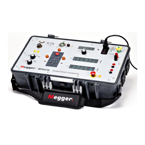
Getting to Know the MTO210 Top Panel Controls Figure 1: MTO210 Front Panel Input AC Power Module: This module is an IEC320 interface to the mains power. The module has an integrated switch, fuse holder and input filter module. Above the module are the voltage, frequency and power requirements for the product. - Page 12 Input Voltage V1 These connections are used to connect a transformer winding for input voltage measurement. The instrument will automatically calculate the resistance of this input in combination with the current source. The connectors are also used as a path for current to flow during discharges. Voltage leads shall always be used in conjunction with current leads.
- Page 13 Getting to Know the MTO210 Maintenance Port This port is provided for software upgrades and diagnostics, the interface panel can be removed and an Ethernet connection is available to attach the instrument externally to a PC. Port is NOT network compatible. This product is not intended for network use.
- Page 14 IDLE STATE - When pushed the unit will start a test on a transformer. This will only occur if the instrument is in Test Mode (see Function Mode Switch above). The TEST INDICATOR above the button will illuminate during the test. TEST STATE –...
-
Page 15: Safety
Under certain conditions, this voltage could prove to be lethal. The Megger Transformer Ohmmeter has built-in safety protection thru the VOLTAGE POTENTIAL LEADS. Voltage leads shall always be connected in parallel with the current leads. -
Page 16: General Safety Precautions
General Safety Precautions The MTO and the Unit Under Test (UUT) should both be considered as sources of instantaneously lethal levels of electrical energy. Observe the following safety precautions: Observe all safety warnings on the equipment. They identify areas of immediate hazard that could result in injury or death. -
Page 17: Input Power Precautions
The voltage to ground from the live pole of the power source must be within the following rated operating voltage: For Cat. No MTO210: 120/230 V 10%, single-phase sine, 50/60 2 Hz The neutral pole must be at ground potential. Before making connection to the power source, determine that the instrument rating matches the voltage of the power source. - Page 18 AVTMMTO210 Rev 7 Sept 2013...
-
Page 19: Preparing For A Test
Making Circuit Connections Connections should be made in the order as listed below. 1. Ground. Use the Megger supplied Safety Ground Cable (15 ft (4.6 m)) to connect the MTO Wing Nut Ground Terminal directly to Local Station Earth Ground. Ensure that the Transformer chassis also has a low impedance connection to Local Station Earth ground potential. - Page 20 MTO so they will not become loose even in the event of the operator inadvertently tripping over the current leads. MTO210 is programmed to read two voltage inputs at all times. If a voltage input is not used, the high impedance input characteristics of the input cause the unit to give readings that are not zero.
- Page 21 Safety At this time, make the connections to the Transformer Under Test (TUT), as described in the applicable section of Section 5, Connecting to the Transformer Under Test. AVTMTO210 Rev 7 Sept 2013...
- Page 22 AVTMMTO210 Rev 7 Sept 2013...
-
Page 23: Operating The Mto210
Operating the MTO210 When testing high-voltage transformers, caution must be used at all times and all safety precautions followed. Read, understand, and employ all safety precautions and circuit connections described in Section 2 Safety and Section 3 Preparing for Test. - Page 24 If an error code is displayed that is uncorrectable, return the instrument to Megger or an authorized service center for repair. Refer to Section 7 Service for repair instructions. If no errors are detected, the resistance and current displays will present dashes (-).
- Page 25 Operating the MTO210 Press to change the transition sensitivity. 0 is off and the higher the number, the more sensitive the circuit will be for current transitions. Press to turn ON or OFF the OHM 2 display during testing. 7. locally stored temperature that the unit will store with the resulting data for all subsequent tests.
- Page 26 built-in. It will automatically initiate when the current source is disconnected from the transformer. It will also provide visual indication of discharging. DEMAGNETIZATION FUNCTION This button, when pushed will perform a transformer demagnetization. The Demag Indicator to the right will illuminate during the demagnetization cycle.
- Page 27 Operating the MTO210 indicator that you are in Remote Mode and the button is functioning properly. 3. To start a test sequence, press on the front panel. This will NOT cause the test to start but only illuminate the HV Indicator. The Remote Indicator will stay off.
- Page 28 STORED DATA FUNCTIONS The MTO can save up to 2000 test results to memory for archival purposes. If data is stored while testing, the unit can step thru the memory after testing in a review process. TEST 1. Set the Data Output Mode Switch into Storage Review Mode. The unit will come up with the last data stored in alternate mode.
- Page 29 Operating the MTO210 SET TIME FUNCTION The MTO can set the Time of Day from the front panel interface. Set the function mode switch to the Date Time Setting as shown below. TEST 1. Set the Function Mode Switch into set time mode.
- Page 30 2. Press to traverse from year/month/day to month/day/year to day/month/year. 3. Press to confirm any changes made to selected parameters. AVTMMTO210 Rev 7 Sept 2013...
- Page 31 6. Download the file and run. The software will self extract and run automatically. 7. A Megger Welcome Screen will appear on the PC display. Before moving forward connect the PC to the MTO210 via an Ethernet cable. 8. Follow the instructions on the screen and the software will guide you...
- Page 32 AVTMMTO210 Rev 7 Sept 2013...
-
Page 33: Transformer Testing
Transformer Testing WARNING When testing a transformer or regulator, make sure that a good ground is placed on the test specimen as shown on all connection diagrams. Winding Resistance Testing Winding resistance measurements in transformers are of fundamental importance for the following purposes: Calculations of the I2R component of conductor losses. -
Page 34: Testing A Single-Phase Transformer
wye-connected winding or between pairs of terminals on a delta-connected winding. Comparison may also be made with original data measured in the factory. Testing a Single-Phase Transformer SINGLE-WINDING TEST Figure 2: Single Winding Measurement WARNING Do not disconnect leads until all indicators are OFF! PROCEDURE: 1. - Page 35 Transformer Testing Set to desired MAXIMUM TEST CURRENT. Set to desired DATA OUTPUT. 4. Connect "V1" voltage leads to test specimen winding. Do not clip potential leads on the current leads, since this will add contact resistance to the measurement. See Figure 2. Connect current output (I) to test specimen winding.
-
Page 36: Figure 3: Dual-Winding Test
DUAL-WINDING TEST This procedure describes the testing of both windings (high and low) on a single- phase transformer at the same time. Figure 3: Dual-Winding Test WARNING Do not disconnect leads until all indicators are OFF! NOTES: It should be carefully noted that the jumper in Figure 3 be connected to opposite polarities of transformer to reduce transformer core saturation time. - Page 37 Transformer Testing 3. Set the following conditions: Set to TEST position. Set to desired MAXIMUM TEST CURRENT. Set to desired DATA OUTPUT. 4. Connect "V1" voltage leads input to H1 and H2 terminals of test transformer. See Figure 3. 5. Connect "V2’ voltage leads input to X1 and X2 terminals of test transformer.
- Page 38 Temperature Correction It may be necessary to convert the resistance measurements to values corresponding to the reference temperature in the transformer test report. To estimate the winding temperature at the measurement is important. If the transformer has winding temperature, use theses readings. If not, the winding temperature is assumed to be the same as the oil temperature under the following conditions: The transformer has been out of service for at least 3 hours...
-
Page 39: Figure 4: Reading Obtained Is Per Phase, Resistance Of A-N Winding
Transformer Testing Testing a Three-Phase Transformer The following details the different methods to be used in testing three-phase transformers. The measurements taken will be for one or two winding(s) at a time. Connection diagrams (Figures 4 thru 7) are to be used in conjunction with procedure "Single-Phase Transformer Test". -
Page 40: Figure 5: Reading Obtained Is Between Pairs Of Terminals, Resistance Of A And B Windings
2. Three-Phase Wye Configured Winding, No Neutral Brought Out Figure 5: Reading obtained is between pairs of terminals, Resistance of A and B Windings Use the above diagram in conjunction with procedure "Single-Phase Transformer Test". 3. Three-Phase, Delta Configured Winding Figure 6: Reading is between pairs of terminals. -
Page 41: Testing Delta Configured Windings
Transformer Testing Testing Delta Configured Windings Testing Delta winding resistance may be a very time consuming procedure, in particular LV winding deltas the correct balance time can take up to 30-60 minutes for a large transformer, which far exceeds the time restriction of many tests. - Page 42 TABLE 1. EXAMPLES ON TRANSFORMER CONNECTION SCHEMES INJECTING TEST CURRENT AND MEASURING TWO WINDINGS SIMULTANEOUSLY Measurement setup Vector Group Current Connections Meas ch 1 Meas ch 2 + Current Jumper - Current H3-X1 H1-X2 H2-X3 H3-X0 H1-X0 Dyn7 H2-X0 H3-X1 H1-X2 Dyn1 H2-X3...
-
Page 43: Testing Transformers With Tap Changers
Transformer Testing Testing Transformers with Tap Changers Many transformers used today have taps built into them. These taps allow ratio to be increased or decreased by a few percent. Any of the ratio changes involve a mechanical movement of a contact from one position to another. It is this contact that needs to be checked by way of its contact resistance and mechanical integrity. -
Page 44: Testing Voltage Regulators
Testing Voltage Regulators This procedure describes the basic connections to a single-phase regulator. The main test for a regulator is the evaluation of the condition of the tap positions. Because there are a large number of taps (typical 15 to 32), this test would normally take a very long time. -
Page 45: Figure 9: Connection To A Regulator
Transformer Testing Figure 9: Connection to a Regulator WARNING Do not disconnect leads until all indicators are OFF. PROCEDURE 1. Connect line cord to unit and plug into 120/240V socket. 2. Set the following conditions: Set to TEST position. Set to desired max test current. Set DATA OUTPUT MODE. - Page 46 3. Connect "V1" voltage leads to test specimen winding. See Figure 9. 4. Connect current leads (I) to test specimen winding. Do not clip voltage leads on to the current leads, since this will add contact resistance to the measurement. Voltage leads should always be placed inside (between) the transformer and the current leads.
-
Page 47: Demagnetizing A Transformer
Transformer Testing 4. When measurements are complete, press to terminate and discharge current. Discharge is complete when the discharge indicator is off. Demagnetizing a Transformer The MTO demagnetizes the transformer by automatically magnetizing the core of the transformer in the positive and negative direction with multiple cycles of reduced current. - Page 48 AVTMMTO210 Rev 7 Sept 2013...
-
Page 49: Mto210 Series Powerdb Lite
Introduction PowerDB Lite is a free, but limited capability, version of the PowerDB software tool that is designed specifically to control and/or extract data from Megger instruments. The primary difference between PowerDB Lite and PowerDB is that PowerDB is designed to work with all manufacturers’ equipment and has field and office synchronization capabilities. -
Page 50: Software Installation
Allows all of your field test data to be integrated with CMMS systems such as Maximo or SAP Imports >From Many Other Industry Standard Software Applications Controls and Imports Data from many non-Megger Instruments Software Installation To install PowerDB Lite, load the PowerDB Lite CD into your CD-ROM drive and follow the on-screen instructions. - Page 51 MTO210 Series PowerDB Lite 2. Choose the destination location for the PowerDB Lite files. 3. Select Default Settings. AVTMTO210 Rev 7 Sept 2013...
- Page 52 4. InstallShield Wizard will complete the installation of PowerDB Lite. Click Finish to close the installation program. AVTMMTO210 Rev 7 Sept 2013...
-
Page 53: Using Powerdb Lite
MTO210 Series PowerDB Lite Using PowerDB Lite 1. HOME Select your Instrument MTO210 from the Instrument Setup screen. a. You can always view the Instrument Setup screen from the Tools menu or F3. b. The MTO uses serial communication. Select the appropriate communication settings on the Serial Device Configuration screen. - Page 54 d. Click OK on the Instrument Setup Screen to finish. 2. SELECT A FORM Once you have defined the instrument, PowerDB will present the forms created in the database and associated with that instrument. The factory default form is 56352. AVTMMTO210 Rev 7 Sept 2013...
- Page 55 MTO210 Series PowerDB Lite 3. ENTER TEST DATA a. Header and nameplate information can be manually typed into a form. b. Download Test Data – Pressing this screen button will automatically download all of the data from the MTO. c. Delete Selected Records – When PowerDB Lite is connected to the MTO, the user can select tests from the list of displayed downloaded tests and delete those specific tests.
- Page 56 5. SAVE THE DATA a. Select the File>Save menu item, or press CTRL+S, or press the Save toolbar button. b. The Save As screen will allow you to specify a location and file name for your PowerDB Lite XML file. AVTMMTO210 Rev 7 Sept 2013...
- Page 57 MTO210 Series PowerDB Lite 6. OPENING AN EXISTING FILE a. Select the File> Open menu item. b. Browse to the file you would like to open. c. Press the Open dialog button. d. If the file contains multiple test dates, select the Date that you would like to open for editing or select New to append a new set of results to the file.
- Page 58 7. SETTING THE LOGOS a. Select the Tools>Options menu item. b. The Logos section specifies paths to the left and right logos files to use. c. To change the left logo press the “…” button by the left logo path. d.
- Page 59 MTO210 Series PowerDB Lite 8. HOW TO CHANGE LANGUAGES a. Select the Tools>Options menu item. b. Select the appropriate language in the dropdown menu. 9. HOW TO CHANGE UNITS OF MEASUREMENT a. Select the Tools> Options menu item. b. Select the units in the drop down Default Units under Measurements.
-
Page 60: Frequently Asked Questions (Faq's)
10. ADDITIONAL NOTES a. Additional forms can be filled out by repeating steps 2, 3 and 6. b. Forms can be printed with the File>Print menu item, or type CTRL+P, or press the Print toolbar button. c. A help guide may be found in the Help>PowerDB Lite Help menu item. -
Page 61: Service
Service Maintenance Maintenance should be performed only by qualified persons familiar with the hazards involved with high-voltage test equipment. Read and understand Section 2, Safety, before performing any service. Routine maintenance is required for the MTO test set. The appearance of the MTO test set can be maintained by occasionally cleaning the case, panel and cable assemblies. -
Page 62: Calibration
To replace fuse(s), proceed as follows: 1. Disconnect the power cord from the MTO test set. 2. Using a small flathead screwdriver, carefully remove the fuse holder of the input power module installed on the right side of the MTO test set front panel. -
Page 63: Repairs
In the event that Service is required, contact your Megger representative for a product Return Authorization (RA) number and shipping instructions. Ship the product prepaid and insured and marked for the attention of the Megger Repair Department. -
Page 64: Error Codes
If the error persists, review the possible causes and determine if you can resolve the problem on site. If the basic cause a ruled out, contact Megger for additional assistance. Bold Error codes are quite common with the possible causes defined. - Page 65 Service CODE Error Description Possible Cause Onboard 5 volt supply out of range, too high Onboard 10 volt out of range, too high Onboard 28 volt out of range, too high VICOR power supply temperature is out of range Discharge circuit temperature is out of range 2.5V reference is out of range Zero reference is out of range...
- Page 66 CODE Error Description Possible Cause reference Too much voltage ripple for the VICOR power supply at 5 volts Too much voltage ripple for the VICOR power supply at 20 volts Too much voltage ripple for the VICOR power supply at 40 volts UNDER status input failed OVER status input failed EEPROM byte writing error...
- Page 67 Service CODE Error Description Possible Cause Onboard 10v out of range, voltage too low Onboard 28v out of range, voltage too low Discharge temperature is out of range, too Unit overheated, fans filters clogged, fans high not working, overuse, extremely hot test conditions VICOR temperature is out of range, too Unit overheated, fans filters clogged, fans...
- Page 68 CODE Error Description Possible Cause ADC channel 4 failed HARDWARE_ERROR Discharge takes too much time VICOR protection failed, OVER is too long or too short to reset VICOR protection failed, OVER is too long or too short to set VICOR fast protection failed, OVER is too long or too short to reset VICOR fast protection failed, OVER is too long or too short to set...
- Page 69 Service CODE Error Description Possible Cause Relay test K2 off test failed Relay test K3 on and K4on failed Relay test K3 off test failed Relay test K4 off test failed OVER and UNDER failed during winding resistance test Current calibration failed during winding resistance test Voltage calibration failed during winding resistance test...
- Page 70 CODE Error Description Possible Cause Current = 0 Over didn't stay set for normal transistor protection test Over didn't stay set for fast transistor protection test Transistor protection med-low failed, OVER is too short to reset Transistor protection med-low failed, OVER is too short to set Fast transistor protection high failed, OVER is too short to reset...
-
Page 71: Parts List And Optional Accessories
Parts List and Optional Accessories Item Cat. No. Transformer Ohmmeter MTO210 120/230 volt, 50/60 Hz input INCLUDED ACCESSORIES V1 Potential lead set, 60 ft (18 m) 2000-700 V2 Potential lead set, 60 ft (18 m) 2000-701 Current lead set, 60 ft (18 m) - Page 72 AVTMMTO210 Rev 7 Sept 2013...
-
Page 73: Specifications
Specifications 120/230 V, 50/60 Hz, 750 VA INPUT OUTPUT up to 10 mA User Selectable Current Ranges: up to 100 mA up to 1 A up to 10 A up to 50 Vdc Test Voltage: RESISTANCE MEASUREMENT/DISPLAY @ 10A 1 μΩ to 2Ω res. 0.1 uΩ Resistance: @ 1.0A 10 μΩ... - Page 74 AVTMMTO210 Rev 7 Sept 2013...
Need help?
Do you have a question about the MTO210 and is the answer not in the manual?
Questions and answers