Table of Contents
Advertisement
Advertisement
Table of Contents

Related Manuals for Megger MIT510/2


Summary of Contents for Megger MIT510/2
- Page 1 MIT510/2 5kV Digital Insulation Tester USER MANUAL...
-
Page 2: Safety Warnings
SAFETY WARNINGS Safety Warning must be observed during use. The circuit under test must be switched off, de-energised, isolated and checked to be safe before insulation test connections are made. Make sure the circuit is not re-energised whilst the instrument is connected. Circuit connections must not be touched during an insulation test. -
Page 3: Table Of Contents
CONTENTS Safety warnings Symbols used on the instrument are: Cleaning Introduction Caution: risk of electric shock Power lead and charging Caution: refer to accompanying notes Instrument controls and indicators Power On/Off button Equipment protected throughout by Double Test voltage L and M buttons Insulation (Class II) Test start/stop button Equipment complies with current EU directives. -
Page 4: Introduction
INTRODUCTION POWER LEAD AND CHARGING The MIT510/2 is a compact microprocessor controlled high voltage d.c. If the power lead supplied is not suitable for your type of mains outlet, do insulation tester, powered by internal rechargeable battery or mains not use an adaptor. Always use a power lead fitted with the correct plug. -
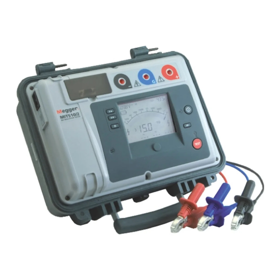
Page 5: Instrument Controls And Indicators
INSTRUMENT CONTROLS AND INDICATORS Voltage at terminals Timer Battery level Analogue display Warning voltage at terminals Warning voltage at terminals Digital display Time constant Capacitance display 1. Check connections to load - see SAFETY WARNINGS 2. To turn on, press Power On/Off button and release after display 8. -
Page 6: Test Start/Stop Button
Test start / stop button Power On/Off button A test will only start if this button is pressed, held and then released as The instrument will only turn on if this button is pressed, held and then soon as the red high voltage warning indicator LED lights. The LCD and released when the display responds. -
Page 7: Line Input Present Led
Line input present LED This is a green LED next to the power On/Off button on the front panel. It is illuminated whenever the mains power is connected. Test terminals There are three test terminals marked +, - and G. These terminals are designed to accept only the test leads supplied. -
Page 8: Battery Bar Graph
Battery bar graph instrument will not perform a test. The high voltage warning indicators flash, and the beeper sounds, to warn of the hazard until the external This is a battery symbol on the LCD display comprising 4 pairs of voltage becomes less than 50 V . -
Page 9: Capacitance Display
These leakages have a significant effect and can occur Alternatively, screened leads are available as an optional accessory from through the air itself. Megger. The lead to the negative terminal is fully screened. The screen is + Test V - Test V plugged into the Guard terminal, diverting any stray leakage currents. -
Page 10: Circuit Block Diagram
SPECIFICATION Circuit block diagram Voltage input range 85-265 V rms, 50/60Hz, 60 VA Battery life Typical capacity is 6 hours continuous testing at 5 kV with a 100 MΩ load 100 MΩ High Test voltages voltage Volts Discharge 250 V , 500 V , 1000 V , 2500 V , 5000 V source resistance Accuracy (23°C, 5 kV) - Page 11 Voltage output accuracy (0°C to 30°C) Humidity +4%, -0% ±10 V of nominal test voltage at 1 GΩ load 90% RH non-condensing at 40°C Current measurement range Dimensions 0.01 nA to 5 mA 305 x 194 x 360 (mm) (12 x 7.6 x 14.2 inches) Current measurement accuracy (23°C) Weight ±5% ±0.2 nA at all voltages...
-
Page 12: Accessories
ACCESSORIES Order Code Included Accessories 3 m lead set, medium size insulated clips 6220-820 User guide on CD-ROM 2000-213 Optional Accessories HV test lead sets 3 x 3 m with un-insulated small clips 8101-181 3 x 8 m with un-insulated small clips 8101-182 3 x 15 m with un-insulated small clips 8101-183... -
Page 13: Repair And Warranty
Megger operate fully traceable calibration and repair facilities, ensuring your instrument continues to provide the high standard of performance and 5. You may track the progress of your return on line at www.megger.com workmanship you expect. These facilities are complemented by a worldwide... - Page 14 F +41 62 768 20 33 F +91 22 26740465 Megger products are distributed in 146 countries worldwide. This instrument is manufactured in the United Kingdom. The company reserves the right to change the specification or design without prior notice.
Need help?
Do you have a question about the MIT510/2 and is the answer not in the manual?
Questions and answers