Megger MTO300 Instruction Manual

Megger MTO300 Instruction Manual

Transformer winding resistance test set
Table of Contents

Advertisement

Quick Links

MTO300
MTO330A
Transformer winding resistance test set
INSTRUCTION MANUAL

Advertisement

Table of Contents
loading
Need help?

Need help?

Do you have a question about the MTO300 and is the answer not in the manual?

Questions and answers

Subscribe to Our Youtube Channel

Summary of Contents for Megger MTO300

  • Page 1 MTO300 MTO330A Transformer winding resistance test set INSTRUCTION MANUAL...
  • Page 2 If the product or its individual instruments are used for purposes other than those specified herein, confirmation of their validity and suitability must be obtained from Megger. Refer to the warranty information below. Specifications are subject to change without notice.
  • Page 3: Table Of Contents

    PowerDB Lite Setup & Installation (PC Control only) ................. 15 Software Installation (PC portion only) ....................16 5 GENERAL TESTING PROCEDURES ....................19 Site Preparation ............................19 Making Circuit Connections ........................19 3 3 3 MTO3XXX-UG-EN Rev 1 Feb 2018 www.megger.com...
  • Page 4 Operating the MTO300/330A ........................ 20 Description of Test Sequence ........................ 21 AUTOMATIC DISCHARGE Function ....................... 21 DEMAGNETIZATION Function ....................... 21 REMOTE TEST Function (MTO300 ONLY) ..................... 22 6 THREE-PHASE TRANSFORMER & WINDING RESISTANCE TESTING ..........25 General ..............................25 Procedure ..............................25 Test Form Controls - General .........................
  • Page 5 Figure 2: MTO330A Front Panel ......................2 Figure 3: MTO330A Optional Controller with Display ............... 4 Figure 4a: MTO Display on Startup ....................... 26 Figure 4b: MTO300/330A using PC Software ..................27 Figure 5: Header Input ........................... 28 Figure 6: Nameplate Input ........................29 Figure 7: Transformer Test Conditions ....................
  • Page 6: Upon Receipt Of Product

    Upon receipt of product Prior to operation, check for loosened hardware or damage incurred during transit. If these conditions are found, a safety hazard is likely, DO NOT attempt to operate equipment. Please contact Megger as soon as possible. MTO300 Transformer Test Set...
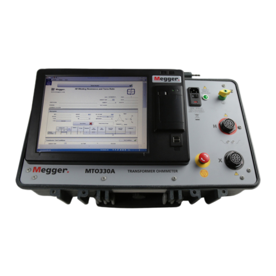
  • Page 7: Product Overview 300/330A

    Product overview 300/330A PRODUCT OVERVIEW 300/330A The Megger Transformer Ohmmeter is a line-operated, field-portable instrument designed specifically to measure the DC resistance of all types of magnetic windings safely and accurately. Its predominant use is the measurement of the DC resistance of all types of transformer windings within the defined range of resistance.
  • Page 8 Primary Interface Connection from the Transformer to the Unit: This connection has all of the interfaces required to connect current and voltage inputs from a three phase transformer into the MTO300 unit. Discharge Indicator – blinks every ½ second when a transformer is discharging Test Indicator –...
  • Page 9 Product overview 300/330A Ethernet Connection: This connection links a PC used for control with the MTO300. NOTE: port is not network compatible. DO NOT USE ON A LOCAL AREA NETWORK. The system was designed for peer to peer operation. Earth/Ground Lug: This connection is used to connect a transformer under test to earth ground for safety.
  • Page 10: Mto330A Top Panel Facilities

    USB Port: Used for various functions including external memory and external mouse/keyboard control. Rear USB Port Hub: Used for external Megger instrument control such as Delta4000, S1/MIT Insulation test set, MLR10. Rear Ethernet Port: Used for external Megger instrument control – specifically the Delta4000, TTR3XX, MLR10, S1/MIT series.
  • Page 11: Safety

    Voltage and High-Power Testing, for additional information. General Safety Precautions The MTO300/330A and the Unit Under Test (UUT) should both be considered as sources of instantaneously lethal levels of electrical energy. Observe the following safety precautions: Observe all safety warnings on the equipment. They identify areas of immediate hazard that could result ƒ...
  • Page 12: Pc Interface Precautions

    Before replacing the fuses, disconnect the power input plug from the live power source. PC Interface Precautions The MTO300 instrument was designed to operate as a peer to peer connection between a Personal Computer with Windows OS and the Test Unit.
  • Page 13: Specifications

    Specifications SPECIFICATIONS Electrical Input Power Cat. No. MTO300/330A: 108-132V, 60 Hz, ±2 Hz, 660 VA (207-253V with fuse change to 4.0 amp*) IEC 1010-1 installation category II Protective Devices (Fuses) Main Input Fuse : Qty 2: 6.3 amp, 250V, 5x20mm, SLO-BLO Qty 2: 4.0 amp, 250V, 5x20mm, SLO-BLO...
  • Page 14: Resistance Ranges

    10 mA 200 Ω to 2000 Ω Guaranteed Accuracy: +/-0.25% Range +/-0.25% rdg Display MTO300: Via external PC (user supplied) MTO330A: Size: 12 inch (305mm), Brightness: 1600 NIT, Operating Temp Range: -10C to +50C operation, Type: 4 wire resistive (touch)
  • Page 15: Physical Data

    Instrument: 8 H x 21.5 W x 13 D in. (216H x 546 W x 330D mm) Weight: MTO300 with standard provided accessories: 29 lbs. (13.1kg) MTO330A with standard provided accessories: 33 lbs (14.9 kg) with Optional Leads, 30 ft (9m)
  • Page 16: Software Installation

    PowerDB Lite software is included at no extra charge software tool that is designed specifically to control and/or extract data from the MTO300/330A. PowerDB Lite will present your test data into a professional looking data form that can be sent to a printer or .pdf file.
  • Page 17 Software installation 1. Accept the terms of the License Agreement. 2. Choose the destination location for the PowerDB Lite files. MTO3XXX-UG-EN Rev 1 Feb 2018 www.megger.com...
  • Page 18 Software installation 3. Select Default Settings (Language and Units of Measure). 4. Install Shield Wizard will complete the installation of PowerDB Lite. Click Finish to close the installation program. MTO3XXX-UG-EN Rev 1 Feb 2018 www.megger.com...
  • Page 19: General Testing Procedures

    4. Connect the Ethernet Cable. If using a remote PC and PowerDB Lite software, connect the Ethernet cable from the MTO330A back panel or the MTO300 front panel to the PC Ethernet port. A standard RJ45 Ethernet cable will work fine for this application. Connect the PC Ethernet output to the MTO300/330A at this time.
  • Page 20: Operating The Mto300/330A

    At this time, make the connections to the Transformer Under Test (TUT), as described in the applicable section of Operating the MTO300/330A When testing high-voltage transformers, caution must be used at all times and all safety precautions followed. Read, understand, and employ all safety precautions and circuit connections described above and in Section 2 Safety.
  • Page 21: Automatic Discharge Function

    NOTE: The demagnetization cycle will take some time for completion. It is equivalent to taking multiple tests in sequence. REMOTE TEST Function (MTO300 ONLY) The main purpose of this function is to take sequential data to storage during a single test. It is useful for tap change testing where multiple resistance values are read in sequence with no interruption in current flow.
  • Page 22 Indicator will flash slowly until a discharge has occurred. The Remote Indicator will slow flash (once per second) (ON,OFF,ON,OFF) to indicate discharging. 13. Press to record the reading again and the process continues until all transformer taps are tested. MTO3XXX-UG-EN Rev 1 Feb 2018 www.megger.com...
  • Page 23: Three-Phase Transformer & Winding Resistance Testing

    7. For PC operation, turn the PC power “ON”. 8. MTO300/330A Start the PowerDB program. For detailed information on PowerDB, please refer to the PowerDB user manual and additionally the Help Screen for the software. The Help screen and PowerDB manuals will stay more up to date than this manual.
  • Page 24: Figure 4A: Mto Display On Startup

    Figure 4a: MTO Display on Startup Figure 4b: MTO300/330A using PC Software MTO300/330A - Select the form desired for use. This manual employs form 3Ø Turns Ratio & Winding Resistance. The form will be displayed and the user will be ready to start the process.
  • Page 25: Test Form Controls - General

    1. IF desired, ENABLE and enter the Header information (see Figure 5 below) with pertinent information. Figure 5: Header Input 2. Enter the transformer nameplate information. The required fields are highlighted below. Figure 6: Nameplate Input MTO3XXX-UG-EN Rev 1 Feb 2018 www.megger.com...
  • Page 26: Transformer Test Conditions

    Test Status: Once testing is complete, indicates condition of the asset under test. iv. Demagnetization: Once depressed, begins demagnetizing transformer winding, and confirms ‘demagnetization’ once complete. Instrument Settings Button Setup the MTO for the desired testing conditions. Figure 8: Instrument Setup Screen – Test Settings/Ω Settings MTO3XXX-UG-EN Rev 1 Feb 2018 www.megger.com...
  • Page 27: Winding Resistance Testing Methods

    Transformer Nameplate Input (Figure 6 above) and Resistance Test Wizard. 2. All phases of a winding tap are measured in sequence – 3. Basic test method where ONLY one reading is measured and taken at a time - MTO3XXX-UG-EN Rev 1 Feb 2018 www.megger.com...
  • Page 28: Method 1 - Resistance Test Wizard

    Test #: Depressing this button commences testing for a specific tap row (circled). Testing is conducted sequentially (up to 2 windings at once), ensuring optimization of magnetized core. Test Current: Records the dc current amplitude recorded for the result. MTO3XXX-UG-EN Rev 1 Feb 2018 www.megger.com...
  • Page 29: Method 3 - Measuring Individual Tap Winding

    Test Mode: Enables various testing to Start, Continue, Save Results etc. as testing is conducted. This button guides operator through testing, providing instruction for next steps. iii. Abort/Exit: Allows disruption of test and/or exiting once test is concluded. MTO3XXX-UG-EN Rev 1 Feb 2018 www.megger.com...
  • Page 30 Item iv above. When condition is reached, background turns green. vii. Reading Stability: Monitors readings, and calculates the change continuously, changing background color to green once Reading Stability Setting is reached. MTO3XXX-UG-EN Rev 1 Feb 2018 www.megger.com...
  • Page 31: Save/Retrieve Results

    Once a file is saved, user has the option to recall the result in numerous ways which are shown below: Within the Instrument Selection window, user is able to open test file for results review, retesting asset or to append existing results. MTO3XXX-UG-EN Rev 1 Feb 2018 www.megger.com...
  • Page 32 Save/retrieve results Once MTO instrument is selected, user can open saved result to view results and/or to retest/append results, or use present form as a template (once settings are entered into form). MTO3XXX-UG-EN Rev 1 Feb 2018 www.megger.com...
  • Page 33: Application Notes

    If the transformer is measured without oil, the winding temperature is normally assumed to be the same temperature as the surrounding air. Once the information and results are in the form, the results can be switched from measured resistance to corrected MTO3XXX-UG-EN Rev 1 Feb 2018 www.megger.com...
  • Page 34 Rs = Rm ( Ts + Tk )/( Tm + Tk ) where Rs = resistance at desired temperature Ts Rm = measured resistance Ts = desired reference temperature Tm = temperature at which resistance was measured Tk = 234.5 (copper) Tk = 225 (aluminum) MTO3XXX-UG-EN Rev 1 Feb 2018 www.megger.com...
  • Page 35: Ordering Information/ Spare Parts

    1010-941 OPTIONAL ACCESSORIES Universal lead sets, compatible with Megger MTO3XX Series products (up to 10 A DC max) 3-phase, 4-wire shielded test leads (H&X), complete with color coded universal Kelvin clamps 3-Ø shielded test lead set, X/H windings, 30 ft (9.1m) 2008-30-KIT 3-Ø...
  • Page 36: Service

    5. Reinstall the fuse holder in its receptacle in the input power module. Connect the power cord to the MTO test set and to an energized power source. If the electronic circuits still do not function properly, contact the factory for service. MTO3XXX-UG-EN Rev 1 Feb 2018 www.megger.com...
  • Page 37: Calibration

    If the error persists, review the possible causes and determine if you can resolve the problem on site. If the basic cause is ruled out, contact Megger for additional assistance. Bold Error codes are quite common with the possible causes defined.
  • Page 38 EEPROM is uninitialized Discharge temperature too much ripple 5V5 voltage out of range 5V5 voltage too much ripple VICOR power supply failed at 5v, voltage too high VICOR power supply failed at 5v, voltage too low MTO3XXX-UG-EN Rev 1 Feb 2018 www.megger.com...
  • Page 39 VICOR fast protection failed, OVER is too long or too short to set Current Regulation failed at DAC=0 Current Regulation failed at 10mA range Current Regulation failed at 100mA range Current Regulation failed at 1A range Current Regulation failed at 10A range MTO3XXX-UG-EN Rev 1 Feb 2018 www.megger.com...
  • Page 40 Fast transistor protection high failed, OVER is too short to reset Fast transistor protection high failed, OVER is too long to set Fast transistor protection high failed, OVER is too short to set MTO3XXX-UG-EN Rev 1 Feb 2018 www.megger.com...
  • Page 41 Relay K1 and K2 failed, current too low Relay K3 and K4 failed, current too low ESD Abort signal encountered Switch pushed down during test Vicor failed during charge Current rising too fast during charge Charge timeout error. MTO3XXX-UG-EN Rev 1 Feb 2018 www.megger.com...
  • Page 42 Manufacturing sites Megger Limited Megger GmbH Megger USA - Valley Forge Archcliffe Road Weststraße 59 Valley Forge Corporate Center Dover 52074 2621 Van Buren Avenue Kent Aachen Norristown Pennsylvania, 19403 CT17 9EN Germany ENGLAND +49 (0) 241 91380 500 1-610 676 8500 +44 (0)1 304 502101 info@megger.de...

This manual is also suitable for:

Mto330a

Table of Contents