
Related Manuals for Megger MIT520/2


Summary of Contents for Megger MIT520/2
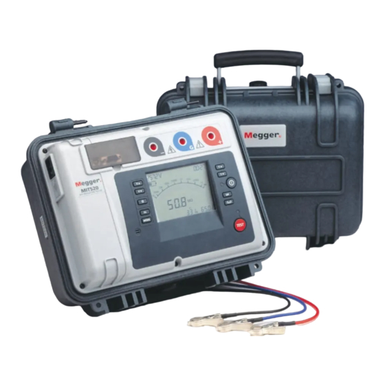
- Page 1 MIT520/2 5kV Digital Insulation Tester 99 Washington Street Melrose, MA 02176 Phone 781-665-1400 Toll Free 1-800-517-8431 USER MANUAL Visit us at www.TestEquipmentDepot.com...
-
Page 2: Safety Warnings
SAFETY WARNINGS Safety Warning must be observed during use. The circuit under test must be switched off, de-energised, isolated and checked to be safe before insulation test connections are made. Make sure the circuit is not re-energised whilst the instrument is connected. Circuit connections must not be touched during an insulation test. -
Page 3: Table Of Contents
CONTENTS Safety warnings Breakdown mode / burn mode Introduction Alarm limit mode General description Step voltage ‘SV’ test Features Polarisation index ‘PI’ test, and dielectric absorption Cleaning ratio ‘DAR’ test Power lead and battery charging Dielectric discharge ‘DD’ test Instrument controls and indicators Measurements above 100 GΩ... -
Page 4: Introduction
The dielectric absorption ratio is automatically calculated if the The MIT520/2 can be powered from the mains supply or by its own corresponding timers are set. internal rechargeable battery, which provides for at least 6 hours of Either burn or breakdown selectable in insulation resistance mode. -
Page 5: Power Lead And Battery Charging
POWER LEAD AND BATTERY CHARGING If the power lead supplied is not suitable for your mains connection, do not use an adaptor. Always use a power lead fitted with the correct plug. The instrument is fitted with a two-pin IEC60320 power inlet. Most power leads are made with three-core cable, so the ground connection will not be used. -
Page 6: Instrument Controls And Indicators
INSTRUMENT CONTROLS AND INDICATORS Line RS232 Measurement terminals Voltage at Test modes Burn indicator Alarm Data recording input guard terminals Time L and Battery level M selectors Timers Main, T1, Voltage L M selectors Line input Present Breakdown Analogue indicator indicator display Power on/off... -
Page 7: Power On/Off Button Test Voltage L And M Buttons
Power On/Off button When the test has stopped, the display continues to show the voltage present on the test leads. Pressing either test voltage L or M button will The instrument will only turn on if this button is pressed, held and then then display the test voltage immediately before the end of the test. - Page 8 In the ‘IR’, ‘PI’, and ‘DD’ modes the secondary display initially shows the PI (polarity index), DAR (dielectric absorption ratio), and, on completion of the test, the TC (time constant) and capacitance measurements. Toggling the display shows insulation resistances and currents. In the ‘SV’...
- Page 9 Press Ω/I Press Ω/I Press Ω/I Press Ω/I Press Ω/I Press Ω/I Figure 2 - The result of a polarity index test (PI) Figure 3 - The result of a dielectric discharge test (DD) Test settings: T1 and T2 times set in order to measure the DAR Test settings: T1 and T2 times set in order to measure the DAR Test conditions: timer defaults to 10 minutes, as this is required for a PI Test condition: test runs for longer than 10 minutes as this is required for...
-
Page 10: B Button
test voltage buttons. ‘TL and ‘TM represent the timer buttons. Button Press Function Comment Fn + VL Increment in 10 V steps Voltage range between 50 and 1000 V Fn + VM Decrement in 10 V steps Voltage range between 50 and 1000 V Fn + VL Increment in 25 V steps... -
Page 11: Record Button
The instrument now discharge. Megger Limited cannot accept responsibility for any losses of displays ‘clr’ to indicate clear mode. Press and hold down test button until data. -
Page 12: Recording To A Pc
Recording to a PC terminal i.e. if the insulator is clean and there are unlikely to be any adverse current paths. However in cable testing for example, there may be surface While carrying out a test, the instrument will output the test voltage, test leakage paths across the insulation between the bare cable and the external current and resistance every second. -
Page 13: Rs232 / Usb Connections
Installation instructions are also to be found on the CD. If there is an external voltage greater than 50 V present, this will be Programmes such as Megger Download Manager may be used to displayed regardless of changes made to the test voltage. In this case the ®... -
Page 14: Analogue Display
shows the last measurement made until the timer or voltage test settings ‘Pre-Test / During test’ Key action table. are changed, or the test start/stop button is pressed. Button press Key action Fn + Key action Analogue display Pre-test During test Pre-test During test This simulates an analogue meter movement to give the user a better... -
Page 15: Test Mode Summary
TEST MODE SUMMARY Pressing the ‘Ω/I’ button toggles the display to show the insulation Press the ‘MODE’ button to cycle through and select the test mode. resistances, insulation currents, DAR and PI ratios, and capacitance. The Modes of test to be chosen from include an insulation resistance ‘IR’ test, a resistances and currents will be displayed under the ‘T1’, ‘T2’, ‘1m’... -
Page 16: Step Voltage 'Sv' Test
any absorption effects are masked by high leakage currents. On to set the resistance threshold between the limits of 10 kΩ and 15 TΩ. completion of the test the polarisation index is displayed under the Release the function button to save the current limit. Adjusting the alarm segment heading ‘PI’. -
Page 17: Measurements Above 100 Gω
other current component, comprising the released absorption current, Measurements above 100 GΩ decays from a lower value with a relatively long time constant of up to Measurements up to 100 GΩ can be made without any special precautions, several minutes. If this component of the discharge current is large (>7 @ assuming that the test leads are reasonably clean and dry. -
Page 18: Circuit Block Diagram
For 10 kV instruments C1 = 15 nF, R1 = 156 kΩ, R2 = 110 kΩ Alternatively, screened leads are available as an optional accessory from Megger. The lead to the negative terminal is fully screened. The screen is plugged into the Guard terminal, diverting any stray leakage currents. This considerably improves measurements made with a floating output, where the leads might touch each other or anything other than the test piece. -
Page 19: Specifications
<120 ms per µF to discharge from 5 kV to 50 V current, and insulation resistance. The PI, DAR, capacitance, time constant and DD values are also stored if available at the end of the test. Megger Capacitance measurement (500 V minimum test voltage) Download Manager may be used to transfer this data to a PC. -
Page 20: Accessories
25955-025 Meets the requirements of IEC61326-1 USB cable 25790-041 Operating uncertainties Optional Accessories Refer to www.megger.com HV test lead sets Operating temperature 3 x 3 m with un-insulated small clips 8101-181 -20°C to 50°C 3 x 8 m with un-insulated small clips... -
Page 21: Repair And Warranty
RA number. 5. You may track the progress of your return on line at www.megger.com Approved Service Centres A list of Approved Service Centres may be obtained from the UK address Visit us at www.TestEquipmentDepot.com...
Need help?
Do you have a question about the MIT520/2 and is the answer not in the manual?
Questions and answers