Megger MFT1800 Series User Manual
Multifunction testers
Hide thumbs
Also See for MFT1800 Series:
- Quick start manual (9 pages) ,
- Quick start manual (8 pages) ,
- User manual (70 pages)
Table of Contents
Advertisement
Quick Links
Advertisement
Table of Contents

Subscribe to Our Youtube Channel
Related Manuals for Megger MFT1800 Series


Summary of Contents for Megger MFT1800 Series
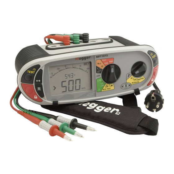
- Page 1 MFT1800 series Multifunction testers User manual...
-
Page 2: Table Of Contents
Contents SAFETY WARNINGS Introduction Overview Front panel and controls Waste electrical and electronic equipment Battery and Fuse Location, fitting and replacement Operation General operation – all models Mode button functions Test inhibit Voltage, Frequency, Current and temperature measurement Making a voltage measurement Continuity / resistance measurement Nulling test lead resistance (up to 9.99ohms) Making a CONTINUITY measurement... - Page 3 Earth resistance measurement Connection terminals Touch voltage limit Two terminal resistance measurement Three terminal resistance measurement Three terminal resistance measurement using ART (MFT1825, MFT1835) Two-clamp stake-less measurement MFT1835 only SETUP OPTIONS Warning messages 11.1 Startup warnings 11.2 Battery 11.3 Battery charger 11.4 Fuse warning 11.5...
- Page 4 SAFETY WARNINGS Safety Warnings and Precautions must be read and understood before the instrument is used. They must be observed during use. ■ The circuit under test must be switched off, de-energised and isolated before test connections are made when carrying out insulation and continuity tests.
- Page 5 LIVE EARTH SAFETY PRECAUTIONS A ‘Live’ earth is one that carries current from the mains supply, or could do so under fault conditions. The following warnings apply in addition to those listed previously. ■ All persons involved must be trained and competent in isolation and safety procedures for the system to be worked on. They must be clearly instructed not to touch the earth electrode, test stakes, test leads, or their terminations if any ‘Live’...
-
Page 6: Introduction
Introduction Congratulations on your purchase of a genuine Megger Multifunction tester. The MFT1700 and MFT1800 series Multi-function tester is a compact instrument designed to perform all of the functions required by the electrical contractor to fully test domestic, commercial and industrial wiring. Specially designed to comply with U.K., European and other International wiring regulations and standards, the MFT1800 may be used on all single and three phase systems with rated voltages up to 300 Volts a.c. - Page 7 2.1.1 Display Display symbols Symbol Meaning Symbol Meaning Test function locked on (also used to indicate a Warning triangle – instruction to refer to this change is saved in setup) user guide Test lead null active Fuse blown Touch voltage limit (and Earth test voltage) set to Battery indicator 50 V (change setup) NiMH...
-
Page 8: Waste Electrical And Electronic Equipment
Waste electrical and electronic equipment WEEE The crossed out wheeled bin placed on Megger products is a reminder not to dispose of the product at the end of its life with general waste. Megger is registered in the UK as a Producer of Electrical and Electronic Equipment. The... - Page 9 Spent Alkaline and NiMH batteries are classified as Portable Batteries and should be disposed of in the UK in accordance with Local Authority requirements For disposal of batteries in other parts of the EU contact your local distributor. Megger is registered in the UK as a producer of batteries. The Registration number is BPRN00142...
-
Page 10: Operation
Operation General operation – all models 3.1.1 Switching on Turn the rotary knob away from the off position. The instrument will perform internal self tests then display the appropriate test screen, depending on the position of the function knobs. 3.1.2 Switching off Turn the primary function knob to the OFF position. -
Page 11: Test Inhibit
Test inhibit Each test mode has conditions under which testing will be inhibited, as below: 3.3.1 Insulation Detection of a circuit voltage above 50 V (a warning is displayed at 25 V) 3.3.2 Continuity Detection of a circuit voltage above that used by the instrument will inhibit testing. 3.3.3 Earth loop impedance Touch voltage exceeds 50 V (or 25 V depending on instrument configuration) Supply voltage over range or under range... -
Page 12: Voltage, Frequency, Current And Temperature Measurement
Voltage, Frequency, Current and temperature measurement Making a voltage measurement .1 Set the Main rotary range knob to volts (The position of the right hand rotary range knob does not matter) .2 Using two or three test leads, connect test leads to the L1, L2 and L3 terminals OR if Using the Mains plug Lead: Note: When all three test leads (eg Phase, Neutral and Earth) or the mains plug test leads are connected, the voltage displayed is the highest of the three possible voltages and the supply frequency is shown in the secondary display. - Page 13 Frequency measurement .1 Automatically displayed when connecting to a live circuit as per 4.1 above Phase rotation Display of Phase rotation is Automatic when all three test leads are connected to the 3 phase supply as below: .1 Set the Main rotary range knob to volts (The position of the right hand rotary range knob does not matter) .2 Using three test leads, connect test leads to the L1 to Phase1, L2 to Phase 2 and L3 to Phase 3.
- Page 14 Switch probe In the V/mV/ºC mode all measurements except temperature can be made with the remote switch probe. Tests are automatic and do not require the test button to be pressed. .1 Connect the switch probe to the switch probe socket. The probe replaces the standard RED test lead and can now be used as a normal test probe.
-
Page 15: Continuity / Resistance Measurement
Continuity / resistance measurement IMPORTANT The continuity test will auto-range from 0.01Ω to 99.9kΩ. Circuits up to 2Ω will be tested at >200mA. To change the test current, go to section 10 – Setup. The continuity test is automatic. The test starts as soon as the leads are connected to a circuit. The TEST button is ONLY used to null the lead set. -
Page 16: Making A Continuity Measurement
Making a CONTINUITY measurement .1 Set the Primary (Left) range knob to range. (The position of the right hand rotary range knob must not be in the position). .2 Connect two test leads to the L1 (+ve) and L2 (-ve) terminals on the instrument. A continuity measurement is made automatically. -
Page 17: Switch Probe (Sp5)
Switch probe (SP5) In the CONTUNUITY/RESISTANCE mode all measurements can be made with the remote switch probe (SP5). Tests are automatic and do not require the TEST button to be pressed. .1 Connect the switch probe to the switch probe socket L1 (+ve). The switch probe replaces the standard RED test lead. Test as in 5.2 above. -
Page 18: Insulation Resistance
Insulation resistance IMPORTANT: The insulation test is protected by a live circuit warning. Detection of a voltage over 50V will inhibit testing. This applies whether or not the insulation test is locked on. Making an INSULATION measurement .1 Set the left hand rotary range knob to the insulation test voltage required: .2 Connect two test leads to the L1 (+ve ) and L2 (-ve) terminals on the instrument. -
Page 19: Measurement Methods And Sources Of Error
Live circuit warning - operates when connected to Live circuits > 25V. Testing is still permitted. Test Inhibited - Live circuits greater than 50V will inhibit testing. Measurement methods and sources of error Method of measurement The selected dc test voltage (current limited to less than 2mA d.c).is applied to the circuit under test and the resistance is calculated from measurements of the resulting voltage and current. -
Page 20: Loop Impedance Testing
The right hand knob should be set to any of the “RCD” or “Re” ranges. Connecting the 3rd (Blue) lead enables the “3 wire loop test” 3Lo, as below and enables “reverse polarity detection”. Test Options in L-PE mode: In L-PE mode the MFT1800 series offer 3 types of loop test:... - Page 21 3Lo – A 3-wire low current loop impedance test. This test requires all three connections. Where to use: For making L-E measurements on circuits where all three conductors are available AND the Phase – Earth circuit is RCD protected. REQUIRES ALL THREE TEST LEADS TO BE CONNECTED 2Hi –...
-
Page 22: Making A Loop Impedance Measurement
In L-N (L-L) mode the MFT1800 series offers one type of loop test: 2Hi – A 2-wire high current test. A fast 3-4 second test using high test currents. Where to use: On ALL circuits except Phase – Earth measurements on RCD protected circuits. - Page 23 The 3rd test lead can be connected to Neutral (L3) but is not used in the ‘2Hi’ Phase-Earth measurement. With the 3rd lead connected the MFT will show a Phase-Neutral reversed connection if present. A warning is displayed if there are any disturbances to the circuit under test during the test sequence. The display will show the symbol.
- Page 24 .4 Press ‘TEST’ to start the test sequence. This can be automated in SETUP so the test starts when contacting the circuit. See section 10 Setup. .5 On completion of the test, the display will show the loop resistance on the large display segments, and the fault current on the small display segments.
-
Page 25: Phase To Neutral (Or Phase To Phase) Testing
Using 2 wire measurement – 2Lo L-PE .1 Set the LEFT rotary range knob to the range. .2 Press the Function key <-> to select the “2Lo” mode. .3 Connect test leads as below, with the Red test lead connected to the L1 (Red terminal on the MFT, the Green test lead connected to the Green (L2) terminal. -
Page 26: Prospective Fault Current And Short Circuit Calculation (Pfc & Pscc)
.4 Press and release the TEST button to start the test. .5 On completion of the test, the display will show the loop resistance on the large display segments, and the fault current on the small display segments. Prospective Fault Current and Short Circuit calculation (PFC & PSCC) The prospective fault current and short circuit current of a circuit is automatically calculated when making a loop impedance test. - Page 27 test should not be used on the P-N circuits. Errors can be reduced by:- ■ Use the two-wire lead set with prods and making a firm connection to clean conductors. ■ Make several tests and taking the average. ■ Ensure that potential sources of noise in the installation are isolated (switched off), eg: automatically switched loads or motor controllers...
-
Page 28: Residual Current Device Testing
Residual Current Device testing The MFT1800 series can perform the following RCD tests: 1/2I Non-tripping test at half the rated RCD trip current for 2 seconds, during which the RCD should not trip Tripping test at the rated RCD trip current. The trip time will be displayed Tripping test at 2 x the rated RCD trip current (Only available on MFT 1825 and 1835 instruments) Tripping test at 5 x the rated RCD trip current. -
Page 29: Making An Rcd Measurement
MAKING AN RCD MEASUREMENT NOTES: ■ To select 0º or 180º press and release the mode button whilst in RCD test mode (Note: Type B is not available on MFT1815 instruments) ■ 10mA and 30mA RCD’s should be tested at ½ x I, 1 x I and 5 x I ■... -
Page 30: I Rcd Current Rating (Tripping Test On 30Ma Rcd)
The Display should show the following: Touch voltage limit Measured touch voltage RCD Trip time (No trip) RCD Type RCD Test mode If the RCD Trips, the MFT will flash the “trP” warning and then display the following: .5 Press the mode button to select 180º. -
Page 31: I Rcd Current Rating (Tripping Test On 30Ma Rcd) - Mft1825 & 1835 Only
2 x I RCD Current Rating (Tripping test on 30mA RCD) – MFT1825 & 1835 ONLY .1 Repeat the test sequence in 8.4 but with the LEFT rotary range knob to the RCD test range. .2 Press the mode button to select 0º. .3 Press the TEST button. -
Page 32: Ramp Test
Ramp Test The RCD trip current is measured by applying a test current of half the rated trip current and increasing this every 300 ms (or 500ms for type S RCDs) from 30% to 110% of the RCD current rating. When the RCD trips, the current flowing is recorded and displayed in mA. MAKING A MEASUREMENT .1 Select the appropriate RCD rated current on the right hand rotary switch = 30mA etc. -
Page 33: Type B (Pure Dc) Rcd Test
8.10 Type B (Pure DC) RCD test (MFT1825 and MFT1835 only) ‘Type B’ RCDs are sensitive to pure DC fault currents, as well as pulsed AC and ordinary AC fault currents. First they are tested as Type AC, Type A then type B., using a pure DC test current. Type ‘B’... -
Page 34: Auto Rcd Testing
3 Phase RCD testing The MFT1800 series is designed to test RCDs on 3 phase installations. To test RCDs in a 3 phase system each RCD is tested as a single RCD, from Phase to earth. As described in section 8.1 to 8.5 above. -
Page 35: Touch Voltage Display
8.14 Touch voltage display Touch voltage: The voltage to which an earth conductor may rise during an RCD test. The limit for touch voltage is 50Vac or 25Vac, depending on the environment. Touch voltage is caused by excessive resistance in the earth circuit when a load is placed between the live and earth conductors. Touch voltage is displayed: - at the end of an RCD test the voltage is below the safe limit - before an RCD test is started if it would exceed the safe limit. -
Page 36: Useful Information
8.16 Useful information It is only necessary to test the 10mA and 30mA at 1/2xI, 1xI and 5xI. All other RCDs only need to be tested at 1/2xI and 1xI. Always press the RCD TEST button on the RCD to ensure the function works. It is recommended the RCD test button is tested AFTER the timing tests above are complete. -
Page 37: Earth Resistance Measurement
Earth resistance measurement (not MFT1815) The Megger MFT family of test instruments offers a unique solution to the measurement of earth or ground electrode (rod) supporting 2 and 3 wire measurements: The MFT1825 can use an optional current clamp (ICLAMP) to measure electrode (rod) resistance without disconnection, leaving the installation earthing system intact (Attached Rod Technique, ART). -
Page 38: Three Terminal Resistance Measurement
.2 Set the rotary selector switch to the position. .3 Press and release the TEST button. The instrument will perform pre-measurement check, the status of which will be indicated on the display. The two-terminal resistance reading will be displayed Note: The test voltage used to make the two-terminal resistance reading is a.c. -
Page 39: Three Terminal Resistance Measurement Using Art (Mft1825, Mft1835)
Making a measurements – Three terminal resistance measurement using ART .1 Connect the instrument as BELOW. Position the ICLAMP below the point where the Green Lead is attached to the Earth Conductor. In practice the ICLAMP can be positioned directly on the Electrode under test, at a point below where the green Lead is attached to the the Earth conductor. -
Page 40: Two-Clamp Stake-Less Measurement Mft1835 Only
Two-clamp stake-less measurement (MFT1835 only) .1 Ensure the rotary selector switch is in the OFF position. .2 Connect the instrument as shown in Figure 35. Instrument connection for two-clamp stake-less measurement 12-15V CAT IV 300V 1.2A Electrode under test .3 With this method, the ICLAMP may be positioned directly around the Electrode under test or around the Earth Conductor itself. The ICLAMP should be positioned below the VCLAMP. -
Page 41: Setup Options
Searching for pair *1INS is not available on MFT1815 *2ISC is not available on MFT1815 *3RRA is only available on MFT1800 series To scroll through the options, press the button. Each option will be is displayed in sequence. To change the setting of each function, for example, INS limit alarm from 1MW to 2MW, use the right hand TEST and LOCK keys (also marked with UP/DOWN arrows). -
Page 42: Warning Messages
Warning messages The following warning messages may be displayed during the testing process. Characters which appear in the aux (small) digit field on the display are shown here in a slightly smaller font size. 11.1 Startup warnings “UNC” -Instrument is un-calibrated 11.2 Battery “bAt”... -
Page 43: Loop Test
11.10 Loop Test “trp” -Supply tripped unexpectedly. “>50V” -Test aborted due to danger of exceeding touch-voltage limit. “Err con” -Hardware problem detected during High Current Loop test or RCD test. “hot” -Internal resistors are too hot. Also shows thermometer. “Hot” -Internal heat sink is too hot. -
Page 44: Appendix A - Sending, Storing, Deleting And Recalling Test Results
Appendix A – Sending, Storing, Deleting and Recalling Test Results (MFT1835 only) Table of Symbols Symbol Definition L – E Live to Earth Test L – n Live to Neutral Test n – E Neutral to Earth Test L - L Live to Live Test Circuit Protective Conductor Live... - Page 45 5. If TEST is displayed, this indicates further data is available for the displayed result. Use the LEFT TEST button to display this as required. E.g. for Insulation, the test voltage is available for viewing. Sending stored Test Results via Bluetooth 1. Run Megger Download Manager 2. Using the appropriate driver, follow the on-screen instructions. Sending individual (Blobbing) Test Results Note that in order to Blob test data, the Store Mode needs to be set to Bluetooth or Internal and Bluetooth.
- Page 46 Loop Testing (L-PE) 1. Perform a Loop test as described previously. 2. Press and hold the Bluetooth (Lock) button to send the test result to your PC or mobile device. Release the button when the display chevrons start to alternate. This indicates the connection is being established. When connected, the Bluetooth symbol will flash whilst the result is transmitted.
-
Page 47: Appendix B - Downloading Data Using Bluetooth
Appendix B – Downloading data using Bluetooth® (MFT1835 only) DOWNLOADING DATA VIA BUETOOTH Bluetooth Pairing (PC or Laptop) 1. Turn your MFT ‘on’ to any setting, and turn the smaller dial to the settings (‘spanner’) position to enter the setup mode. 2. - Page 48 Bluetooth Pairing (Windows Mobile 5 Smartphone) 1. Set the MFT Range knob to the Bluetooth SET UP position. 2. Press the Bluetooth (Lock) button on the MFT, the MFT will show ‘- - -‘ if no pairing exists or the last three digits of a paired identity if already paired.
- Page 49 9. Select the ‘Home’ button to return to the main Palm desktop. Bluetooth Pairing (Symbian S60 Version 3) 1. Set the MFT Range knob to the Bluetooth SET UP position. 2. Press the Bluetooth (Lock) button on the MFT, the MFT will show ‘- - -‘ if no pairing exists or the last three digits of a paired identity if already paired.
-
Page 50: Appendix C - Installation Category Definitions
Appendix E – Cleaning and maintenance The MFT1700 and 1800 should only be opened or repaired by an approved Megger service or by Megger instruments Limited. To clean the instrument, use a damp cloth or isopropyl alcohol if available. To clean the display window only use a lint free cloth. - Page 51 By using a current transducer (the Megger ICLAMP) to measure the current flowing through the electrode under test as a fraction of the total test current injected, the instrument can determine the individual resistance. This arrangement is shown below:...
-
Page 52: Appendix G - Repair And Warranty
RA number. 5. You may track the progress of your return on line at www.megger.com Approved Service Centres A list of Approved Service Centres may be obtained from the UK address above, or from Megger’s website at www.megger.com... -
Page 53: General Specification
General Specification Accuracy. Insulation test: 1000 Volts 10 kW – 999 MW ± 3% ± 2 digits 500 Volts. 10 kW – 500 MW± 3% ± 2 digits > 500 MW± 10% ± 4 digits 250 Volts. 10 kW – 250 MW ± 3% ± 2 digits > 250 MW± 10% ± 4 digits 100 Volts. - Page 54 Earth Test Ranges: Intrinsic accuracy: ± 2.0% ± 3 digits. ART Method ± 5.0% ± 3 digits. Stake-less Method ± 7.0% ± 3 digits. Resolution: 0.01 W EN61557 Range: 1.0 W to 1.99 kW Current: 0.45 mA or 4.5 mA. Noise Rejection: 20 V pk/pk (7V rms).
- Page 55 This instrument is manufactured in the United Kingdom. The company reserves the right to change the specification or design without prior notice. Megger is a registered trademark. The Bluetooth ® word mark and logos are registered trademarks owned by Bluetooth SIG, Inc and is used under licence.
Need help?
Do you have a question about the MFT1800 Series and is the answer not in the manual?
Questions and answers