Table of Contents
Advertisement
Quick Links
Elite
SERIES
Owner's Guide
For Model:
ca1155E
Vehicle Security and
Keyless Entry System
IMPORTANT NOTE: The operation of the Security and Convenience System as described in this manual is
applicable to most vehicles. However, due to the configuration of some vehicles, some functions AND/OR
SAFETY PRECAUTIONS may not apply. Please see your installing dealer for more information.
2019 Voxx Electronics Corporation. All rights reserved.
1
Advertisement
Chapters
Table of Contents

Related Manuals for Voxx Electronics Code Alarm ELITE ca1155E


Summary of Contents for Voxx Electronics Code Alarm ELITE ca1155E
- Page 1 IMPORTANT NOTE: The operation of the Security and Convenience System as described in this manual is applicable to most vehicles. However, due to the configuration of some vehicles, some functions AND/OR SAFETY PRECAUTIONS may not apply. Please see your installing dealer for more information. 2019 Voxx Electronics Corporation. All rights reserved.
-
Page 2: Table Of Contents
Table of Contents Using Your Remote Control ..............3 Arming the Security System .............. 3 Bypassing the Shock Sensor ............3 Disarming the Security System ............3 Two Stage Door Unlock (optional) ............. 3 Activating Trunk Release (optional) ........... 3 Activating AUX 1 (optional) .............. -
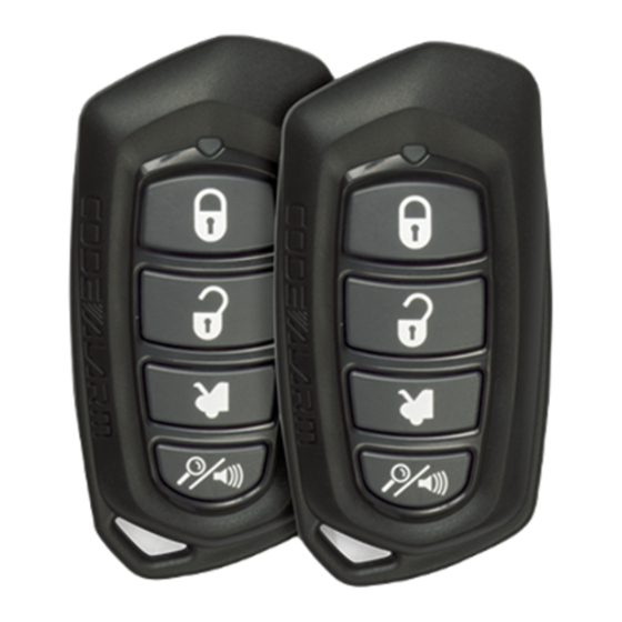
Page 3: Using Your Remote Control
3 seconds will open the vehicle’s trunk or hatch. *Throughout this manual, ‘press’ refers to pressing for less than 1 second; ‘press and hold’ refers to pressing for more than 2 seconds. 2019 Voxx Electronics Corporation. All rights reserved. -
Page 4: Using The Progressive Car Finder Feature
Activating the AUX 1 Output (Optional) If this feature is enabled on your system, pressing the buttons simultaneously will activate an optional feature. This feature can be programmed for a wide range of functions like power window or sunroof automation, please consult your installing dealer to determine the functionality of your system. -
Page 5: User Selectable Led
THE SYSTEM WILL REMAIN IN THIS STATE UNTIL THE BATTERY IS DEPLETED. OVERRIDE THE SYSTEM TO TURN OFF CARJACK MODE: Turn the ignition OFF then On and press the valet button within 10 seconds. 2019 Voxx Electronics Corporation. All rights reserved. -
Page 6: Status Led, Light Flashes And Siren/Horn Indications
Status LED, Light Flashes, and Siren/Horn Indications Status LED Flash Indications LED Flashes Function Disarmed Slow Flash Armed Fast Flash Passive Arming Countdown ON (Solid) Valet Mode 2 Flashes Zone 2 Trigger, Hood / Trunk 3 Flashes Zone 3 Trigger, Door 4 Flashes Zone 4 Trigger, Shock Sensor 5 Flashes... -
Page 7: Remote Control Buttons & Functions
Remove the old battery, observing the +/- symbols on the batteries and replace with a new battery. Reassemble the halves of the remote control and reinstall 1 screw. Test operation of the remote control. 2019 Voxx Electronics Corporation. All rights reserved. - Page 8 LIMITED LIFETIME WARRANTY Applies to Code Alarm Series Control Modules, Sirens, Sensors, and Relays. Voxx Electronics Corporation (the Company) warrants to the original purchaser of this product that should this product or any part thereof, (other than transmitters) under nor-...
- Page 9 Voxx Electronics Corporation. Customer Service 1-800-421-3209 WWW.CODE-ALARM.COM FCC COMPLIANCE This device complies with Part 15 of the FCC rules and with RSS-210 of Industry Canada. Operation is subject to the following two conditions: 1. This device may not cause harmful interference, and 2.
- Page 10 Elite SERIES Installation and Reference Guide ca1155E Security and Keyless Entry 2019 Voxx Electronics Corporation. All rights reserved.
- Page 11 Table of Contents Before You Begin ..................3 Wire Connection Guide ................4 12 Pin Main Harness ................. 6 10 Pin Input / Output Harness ..............9 Door Locks ....................12 Additional Ports ..................13 LED Port ....................13 Programming Port ................... 13 DBI Port ....................
-
Page 12: Before You Begin
Installation Quick Reference Guide that accompanies the Code Alarm system. You can download a printable PDF of the quick reference guide at voxxuniversity.com. Technical Support (800) 421-3209 or go to www.voxxuniversity.com 2019 Voxx Electronics Corporation. All rights reserved. -
Page 13: Wire Connection Guide
Wire Connection Guide System Layout This diagram shows the available harnesses and connection. Note that you may not use all connections and modules in your installation. Programming Note: The default wire function settings are listed next to the wire color. Wires shown with can be programmed to perform different functions. -
Page 14: 12 Pin Main Harness
GROUND WHEN ARMED OUTPUT ( - ) BROWN/BLACK HORN OUTPUT ( - ) VIOLET/BLACK AUX 1 ( - ) GRAY HOOD PIN INPUT ( - ) YELLOW IGNITION INPUT ( + ) RED/WHITE TRUNK RELEASE OUTPUT ( - ) 2019 Voxx Electronics Corporation. All rights reserved. - Page 15 12 Pin Main Harness BROWN SIREN OUTPUT ( + ) Locate a suitable mounting location in the engine compartment for the siren, away from moving parts. With the bell of the siren aiming downwards, secure the siren in place using self tapping screws, being careful not do drill into any hoses, wiring or components.
- Page 16 Connect the WHITE wire to the parking light output wire. Negative switching Parking Lights: Connect the WHITE/RED wire to a good chassis ground. Connect the WHITE wire to the parking light output wire. 2019 Voxx Electronics Corporation. All rights reserved.
- Page 17 VIOLET LOCK POLARITY ( 87 ) Refer to the Door Lock Section on page 11 of this guide. BLUE/BLACK UNLOCK MOTOR ( 30 ) Refer to the Door Lock Section on page 11 of this guide. ca1155E rev B.
- Page 18 This wire will register positive voltage when the door is closed and the interior light is off. Connect the GREEN wire to the vehicle’s negative door input wire(s). NOTE: Certain vehicles may require multiple connections. Refer to vehicle application guide 2019 Voxx Electronics Corporation. All rights reserved.
- Page 19 ORANGE GROUND WHEN ARMED OUTPUT ( - ) This wire will have a continuous ( - ) 300mA output when the system is Armed. This wire is typically used for controlling window modules or additional sensors. BROWN/BLACK HORN OUTPUT ( - ) Locate the vehicle’s horn wire.
- Page 20 Locate the vehicle’s trunk release wire at the trunk release switch. Verification: This wire will register either positive voltage or ground when the trunk release is activated. This is a low current output, 300mA. 2019 Voxx Electronics Corporation. All rights reserved.
-
Page 21: Door Locks
Door Locks BROWN/BLACK UNLOCK SWITCH ( 87A ) BLUE/BLACK UNLOCK MOTOR ( 30 ) VIOLET/BLACK UNLOCK POLARITY ( 87 ) WHITE/BLACK LOCK SWITCH ( 87A ) GREEN/BLACK LOCK MOTOR ( 30 ) VIOLET LOCK POLARITY ( 87 ) The door lock / unlock outputs are designed to control several different types of systems which may require additional parts. 3 Wire Ground Switched Door Locks: Connect the GREEN/BLACK wire to the wire that provides a ground signal from the factory door lock switch to the factory door lock control relay. -
Page 22: Additional Ports
The DBI port is used for external Flashlogic data immobilizer & door lock Interface modules to communicate with the vehicle’s databus. When using the DBI port to control Flashlogic modules please refer to the D2D (Data to Data) function list available per vehicle firmware on the tech service web site. 2019 Voxx Electronics Corporation. All rights reserved. -
Page 23: Digital Tilt / Shock Sensor
Digital Tilt / Shock Sensor The systems digital tilt and shock sensor is onboard and part of the main module. Mount the module to a firm wire harness, or other stable location, that will alow the sensor to pick up vibrations due to impact to the vehicle or if the vehicle is lifted / tilted. When the security system is armed a light impact to the vehicle will trigger the system’s warn-away feature chirping the horn/siren several short times, a harder impact will trigger the system’s full-trigger mode. -
Page 24: Set Up & Programming
2 - 4 chirps. NOTE: The system will remain in feature programming mode as long as the ignition is on, there is no time limit. To exit programming turn the IGNITION OFF. 2019 Voxx Electronics Corporation. All rights reserved. -
Page 25: Shock Sensor Programming, Adjustment And Testing
Manual Feature Programming - Feature Bank 4 & 5 - N/A Reserved for future expansion Shock Sensor Programming, Adjustment and Testing - Feature Bank 6 Turn the ignition ON. Press and hold the valet/override button. Within 10 seconds the system will chirp (3) three times. Use the valet/override button to advance through each option bank. - Page 26 13 Extended Parking Lights After Unlock After Lock Unlock Parking Light Relay / Trunk ( - ) Standard Inverted Output 3 Degrees of 15 Digital Tilt Sensor 1 Degree of Tilt OFF Tilt 2019 Voxx Electronics Corporation. All rights reserved.
- Page 27 Feature Bank 3 - 5 Chirps 1 LED Flash 2 LED Flash 3 LED Flash 4 LED Flash 5 LED Flash 6 LED Flash Output Control 1 Sec. Lock, 30 Sec. Lock, 2x Lock, 1 Sec. Lock / Unlock Timing 3.5 Sec.
- Page 28 Use a PC and VEPROG tool for Feature Programming or Firmware Updates: Launch the Code Alarm Utility App. Connect the VEPROG to your PC via the USB port. Connect the VEPROG to the Code Alarm Module. Select the features you wish to change or update firmware if needed. 2019 Voxx Electronics Corporation. All rights reserved.
-
Page 29: Programming Feature Banks
Dome Light Delay / Theater Dimming The system can be programed to delay arming after the lock button is pressed (60 second max) for vehicles with a dome light delay or theater dimming feature. Once programed the system will ‘learn’ the timing of the dome light delay and add 2 seconds before arming. -
Page 30: Feature Descriptions
The unit will remain armed and may be triggered again. 60 Seconds – When triggered, the system will sound the siren/horn for 60 seconds then stop. The unit will remain armed and may be triggered again. 2019 Voxx Electronics Corporation. All rights reserved. - Page 31 6 - Security: Controls security functionality - ON / OFF. ON - Full security functionality. OFF - The security system does not trigger. Panic and all other convenience features operate as normal. ON w/OEM Remote Start Compatibility - This will prevent a vehicle’s factory remote start from triggering the security system when activated.
- Page 32 3 Degrees of Tilt – The alarm will trigger when the vehicle is tilted 3 degrees. 1 Degree of Tilt – The alarm will trigger when the vehicle is tilted 1 degree. OFF – The tilt sensor is inactive and will not trigger the system. 2019 Voxx Electronics Corporation. All rights reserved.
- Page 33 Feature Bank 3 - Output Control 1 - Lock / Unlock Timing: Controls the timing of the BLUE and GREEN lock output wires. 1 Sec. - Single 1 second lock pulse, single 1 second unlock pulse. 3.5 Sec. - Single 3.5 second lock pulse, single 3.5 second unlock pulse. 1 Sec.
- Page 34 Dome Light Output - Output is used for illuminated entry and is not controlled by the AUX 1 function of the transmitter. Feature Bank 4 & 5 - N/A Reserved for future expansion 2019 Voxx Electronics Corporation. All rights reserved.
- Page 35 Feature Bank 6 - Shock Sensor Programming, Adjustment and Testing Turn the ignition ON. Press and hold the valet/override button. Within 10 seconds the system will chirp (3) three times. Use the valet/override button to advance through each option bank. For Shock Sensor Adjustment advance to Feature Bank 6, which is (8) eight chirps.
-
Page 36: Transmitter Button Functions
Security Trigger Zones If the security system has been triggered the LED will flash one of the patterns below indicating the zone. LED FLASHES TRIGGER ZONE 2 Flashes Hood / Trunk Input 3 Flashes Door Input 4 Flashes Shock Sensor 5 Flashes Ignition Input 6 Flashes Tilt Sensor 2019 Voxx Electronics Corporation. All rights reserved. - Page 37 Programming Note: The default wire function settings are listed next to the wire color. Wires shown with can be programmed to perform different functions. Refer to the Feature Programming section to BROWN SIREN OUTPUT ( + ) change the default setting. BATTERY 12V ( + ) BLACK GROUND...
- Page 38 1. This device may not cause harmful interference, and 2. This device must accept any interference received, including any interference that may cause undesired operation. Warning! Changes or modifications not expressly approved by the party responsible for compliance could void the user’s authority to operate the equipment. 2019 Voxx Electronics Corporation. All rights reserved.
Need help?
Do you have a question about the Code Alarm ELITE ca1155E and is the answer not in the manual?
Questions and answers