Finn HydroSeeder T280 Operator Instructions And Parts Manual
Hide thumbs
Also See for HydroSeeder T280:
- Practical service manual for the parts professional (51 pages) ,
- Parts and operator's manual (84 pages)
Table of Contents
Advertisement
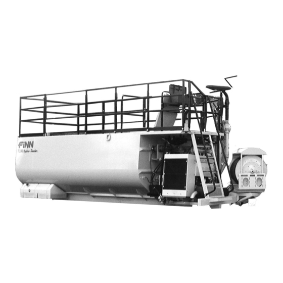
T280 / T330 / T400 HydroSeeder
Operator Instructions and Parts Manual
T280 / T330 / T400
MMA2017 Rev. D
9281 LeSaint Drive • Fairfield, Ohio 45014
Phone (513) 874-2818 • Fax (513) 874-2914
Sales: 1-800-543-7166
Model MMA
Serial No. _____________
Activate
Activate
Your Warranty
Your Warranty
By Registering
By Registering
TODAY!!!
TODAY!!!
®
Advertisement
Table of Contents
Troubleshooting

Related Manuals for Finn HydroSeeder T280


Summary of Contents for Finn HydroSeeder T280
- Page 1 Activate Activate Your Warranty Your Warranty By Registering By Registering TODAY!!! TODAY!!! 9281 LeSaint Drive • Fairfield, Ohio 45014 Phone (513) 874-2818 • Fax (513) 874-2914 Sales: 1-800-543-7166 T280 / T330 / T400 HydroSeeder ® Operator Instructions and Parts Manual Model MMA Serial No.
- Page 2 FOR OFFICE USE ONLY DATE UPDATE DESCRIPTION CODE 02/10/16 Initial release MN0712 09/28/16 Revision A: Part number corrections MN0928 10/12/16 Revision B: new identification light bar MN1012 03/15/17 Revision C: Manual Canister added to unit; added to Structure and Railing parts list MN2017 07/10/17 Revision D: additional agitator shaft seal to design MN2017...
- Page 3 IF FINN CORPORATION DOES NOT HAVE YOUR COMPLETED REGISTRATION FORM ON FILE, YOUR WARRANTY CLAIM WILL BE DENIED. Once your FINN equipment has been registered, your FINN Limited Warranty will be activated per the warranty statement on the next page.
- Page 4 Follow the instruction sheet, on property damage sustained by a person claiming to be a third party how to use your Finn Oil Analysis Kit that comes with the Kit. Failure beneficiary of a surviving warranty under the law of any jurisdiction.
-
Page 5: Table Of Contents
....... 32 - 33 Continued to next page. ® Hydroseeder is a registered trademark of the FINN Corporation... - Page 6 INDEX (Continued) Cleaning and Maintenance ........34 - 35 After First 4 to 8 Hours of Operation.
-
Page 7: Safety First
SAFETY FIRST With any piece of equipment, new or used, the most important part of its operation is SAFETY! FINN Corporation encourages you and your employees to familiarize yourselves with your new equipment and stresses safe operation. The first five pages of this manual are a summary of the main safety aspects associated with this unit. -
Page 8: Hydroseeder ® Safety Summary Section
® HYDROSEEDER SAFETY SUMMARY SECTION It is important that operators of this machine are familiar with all safety aspects covered in this section and have read the entire Operator’s Manual before operating the machine. Always keep a copy of this manual with the machine. It is the responsibility of the operator of the machine to fully understand this safety summary section. - Page 9 II. MACHINE OPERATION (Continued) III. SLURRY APPLICATION (Continued) 6. Operator(s) of equipment should 3. Recirculation valve must be open and material flowing never ride on the machine at speeds back into the tank when using the remote valve. A of greater than 5 mph (8 km/h). closed or plugged recirculation line will cause extreme heat in the pump or discharge lines that will result in severe bodily injury and damage to the equipment.
- Page 10 Drain, flush, and ventilate tank interior. 9. It is recommended that only authorized, genuine FINN Turn off engine, disconnect replacement parts be used on the machine. battery cables, and perform lockout/tagout procedures 10.
- Page 11 COMMON SAFETY DECALS Hazard / Electrical Shock Hearing Hazard Attention Hazard Arc Flash Hazard or Electrocution Fire Hazard Explosion Hazard Hazard Body Electrostatic Fumes / Dust Entanglement Discharge Hazard Hazard Hazard Electrostatic Pinch Point / Burn Hazard Sensitive Area Entanglement Hazard Hazard Explosive or...
- Page 12 COMMON SAFETY DECALS Vision Heavy Object Skin Puncture Protection Hazard Hazard Required Hearing Hot Surface Splash / Spray Protection Hazard Hazard Required Vision, Hearing Loose Clothing and Head Entanglement Stumble Hazard Protection Hazard Required Breathing, Pinch Point / Vision, Hearing Moving Belt Trip Hazard and Head...
- Page 13 COMMON SAFETY DECALS Do Not Ride on Do Not Remove Do Not Obstruct Moving Vehicle Guards or Block Do Not Spray Do Not Touch Power Lines ADDITIONAL SAFETY DECALS WARNING DANGER CONFINED SPACE HAZARD! (Reference: OSHA 29 CFR 1910.146) Before entering tank: 1.
-
Page 14: Operation And Maintenance
FINN T280/T330/T400 HYDROSEEDER ® This manual provides instructions for the operation and maintenance of the FINN HydroSeeder For best results and to ensure longer life of the equipment, please follow these instructions carefully. For your safety, read the entire manual before operating this unit. -
Page 15: Truck Mounting Calculations
TRUCK MOUNTING CALCULATIONS (WB x FL) – (WB x FE. . G ..HW WB x (RE + HW -RL. . G ..HW G + C must be equal to or less than CA (WB x FE) + (G x HW. -
Page 16: Mounting The Hydroseeder
Place hard wood spacers along the length of truck rails or use FINN spring mounting kit (part number 011562) or equivalent. The T400 requires (2) Spring Mounting Kits. ATTACHMENTS 1. -
Page 17: Pre-Start Check
ATTACHMENTS (CONTINUED) 2. For lower-pressure applications, or for close-up work, i.e. around buildings, the remote valve attachment can be used. The attachment includes semi-rigid hose with quick-disconnect fittings along with a handheld valve which fits the end of the hose and accepts the standard nozzle assemblies. -
Page 18: Equipment Check
GREASE 2. Remove cap and fill cap with sodium- (water soluble) Figure 3 based grease (FINN part number 000698). Do not use lithium- based (chassis lube) grease. Pressure Lubricator 3. Replace cap. 4. Turn thumb nut counterclockwise until thumb nut is at the top of the stem. The spring and pressure disc in the pressure lubricator forces the grease, under pressure, to the pump seal. -
Page 19: Two-Valve Operation
TWO VALVE OPERATION ® This HydroSeeder is equipped with two independently DISCHARGE VALVE operated ball valves to control slurry flow. One is (SHOWN CLOSED) located in the recirculation line below the platform, and the other is located in the discharge line above the platform. -
Page 20: Extension Hose Or Hose Reel Through Remote Port
TWO VALVE OPERATION (CONTINUED) 3. EXTENSION HOSE OR HOSE REEL THROUGH REMOTE PORT Flow is through recirculation with no flow through closed discharge valve (Figure 6). Flow through hose is controlled by engaging and disengaging slurry pump CLOSED clutch, or by use of the remote valve at end of hose. Opening the recirculation valve allows flow back into tank when the remote valve is closed. -
Page 21: Starting Procedure
STARTING PROCEDURE ® See HYDROSEEDER SAFETY SUMMARY SECTION before operating the machine. Failure to comply could result in death or serious injury. Failure to comply could also result in product or property damage. Before starting, open the recirculation valve, close discharge valve and recirculation valve (if applicable), disengage clutch, and place the agitator control in the NEUTRAL position. -
Page 22: Faceplate
POWERVIEW (CONTINUED) FACEPLATE The keypad on the PowerView is a capacitive touch sensing system. There are no mechanical switches to stick or wear out. It can be operated in extreme temperatures, while wearing gloves, through ice, snow, mud, grease, etc. When the key is touched, feedback is provided by flashing the screen. -
Page 23: Stored Fault Codes
POWERVIEW (CONTINUED) Stored Fault Codes The PowerView Display will store any fault codes generated by the engine and display them along with a text description. To access these fault codes: 1. Touch the Menu Key to display the Main Menu. GO TO 4-UP DISPLAY ENGINE CONFGURATION 2. -
Page 24: Area Coverage - Material Capacity
® The tables on page 17 show loading-versus-coverage rates for the FINN HydroSeeder Table A shows rates for one-step applications. The coverage area is determined by the fiber mulch ®... - Page 25 TABLE A – Using Seed, Fertilizer, and Mulch Unit Amount of Material in Tank in lbs (kilograms) Coverage Area in sq ft (sq m) Seed Fertilizer Mulch T280 287 (130) 333 (151) 1,250 (567) 36,300 (3,372) T330 345 (156) 400 (181) 1,500 (680) 43,560 (4,046) T400...
-
Page 26: Tank Capacity Charts
T280 T280 Gallons in. (cm) from in. (cm) from (Liters) top of load hatch bottom 2,750 (10,410) 8 (20.3) 58.5 (148.6) 2,700 (10,220) 11.75 (29.8) 54.75 (139.1) 2,600 (9,840) 13.75 (34.9) 52.75 (134) 2,500 (9,465) 15.5 (39.4) 51 (129.5) 2,400 (9,085) 17.75 (45.1) 48.75 (123.8) 2,300 (8,705) - Page 27 T330 T330 Gallons in. (cm) from in. (cm) from (Liters) top of load hatch bottom 3,300 (12,490) 9 (29.9) 58.5 (148.6) 3,200 (12,115) 13.25 (33.7) 54.25 (137.8) 3,100 (11,735) 14.75 (37.5) 52.75 (134) 3,000 (11,360) 16.5 (41.9) 51 (129.5) 2,900 (10,975) 18 (45.7) 49.5 (125.7) 2,800 (10,600)
- Page 28 T400 T400 Gallons in. (cm) from in. (cm) from (Liters) top of load hatch bottom 3,975 (15,045) 9 (22.9) 58.5 (148.6) 3,900 (14,762) 10 (25.4) 57.5 (146.1) 3,800 (14,383) 11.5 (29.2) 56 (142.2) 3,700 (14,005) 12.5 (31.8) 55 (139.7) 3,600 (13,626) 14 (35.6) 53.5 (135.9) 3,500 (13,248)
- Page 29 NOTES...
-
Page 30: Loading Procedure
(turn off) clutch. G. Replace nozzle and gasket in discharge boom. 4. Continue filling tank with water. 5. Increase engine speed to full rpm. Governed speed of the engine on the FINN HydroSeeder® should be 2,550 to 2,600 Rpm under load. - Page 31 LOADING PROCEDURE (CONTINUED) 6. Start loading dry material, loading the lightest material first. Agitator control should be in full REVERSE for mixing. A. Seed – Cut open the seed bag and dump contents into slurry tank. (When using in- oculant, add it in the tank along with the seed. When using quick-swelling seeds, load them just prior to application.
-
Page 32: Loading And Mixing Bfm, Fgm, Smm And Other Viscous Slurries
LOADING AND MIXING BFM, FGM, SMM AND OTHER HIGHLY VISCOUS SLURRIES 1. With clutch disengaged (turned off) and agitator control in the NEUTRAL position, start engine and allow it to warm up. See STARTING PROCEDURE page 13. 2. Start filling unit with water using one of the sources of water listed below. When water reaches the top of the agitator paddle blades, move agitator to full REVERSE position. - Page 33 LOADING AND MIXING BFM, FGM, SMM AND OTHER HIGHLY VISCOUS SLURRIES (CONTINUED) 6. Start loading dry material, loading the lightest materials first. Agitator control should be in full REVERSE for mixing. Seed - Cut open the seed bag and dump contents into slurry tank. (When using inoculant, add it in the tank along with the seed.) When using quick-swelling seeds, load them just prior to application.
-
Page 34: Prior To Application
PRIOR TO APPLICATION 1. Operator should familiarize themselves with the area to be seeded and develop a plan to ensure uniform application. 2. Develop a plan for communication between operator and driver of the carrying or towing vehicle to signal for start, stop, turn, etc. through the use of the signal horn. 3. -
Page 35: Application Of Slurry
APPLICATION OF SLURRY I. GENERAL APPLICATION TECHNIQUES Do not spray toward power lines, transformers or other high voltage conductors. Failure to comply WILL result in severe personal injury or death. The driver of the carrying vehicle should remain alert for hazards to the operator, such as low power lines, hanging branches, etc. -
Page 36: Iii. Procedures When Using Hoses
APPLICATION OF SLURRY (CONTINUED) III. PROCEDURES WHEN USING HOSES Always pump clear water through the hose before pumping mulch. If the inside hose liner is dry, it will dewater the mulch, causing the hose to plug. A. PUMP TAKE-OFF SYSTEM OR HOSE REEL WITH REMOTE VALVE 1. -
Page 37: Hose Work With Remote Transmitter
APPLICATION OF SLURRY (CONTINUED) C. HOSE WORK WITH REMOTE TRANSMITTER 1. Begin with the engine around 1/4 throttle (1,400 rpm). 2. Close recirculation valve. If using an extension hose connected to the discharge boom, open discharge valve. If using the hose reel, close discharge valve and open pump take off valve to the hose reel. -
Page 38: Liming With The Hydroseeder
, it is advisable to keep the slurry moving through the pump at all times. This keeps the solids from settling in the lines, and creating a clog. This unit was designed for the application of agricultural-grade lime or FINN-HLL liquid lime only. - Page 39 LIMING WITH THE HYDROSEEDER ® (CONTINUED) 15. With the slurry pump clutch still engaged (turned on), re-open discharge valve to commence application. To decrease pump wear and increase discharge distance, it may, at this point be desirable to close the recirculation valve. However, the recirculation valve must be open BEFORE closing the discharge valve if the application of slurry is to be interrupted.
-
Page 40: Cleaning And Maintenance
CLEANING AND MAINTENANCE AFTER FIRST 4 TO 8 HOURS OF OPERATION Check and adjust clutch – see clutch manual. DAILY ® 1. Cleaning the HydroSeeder A. Fill slurry tank to center of agitator shaft with clean water. B. Move agitator lever to full speed to flush off inside of tank top and walls. C. -
Page 41: Weekly Or Every 40 Hours Of Operating Time
CLEANING AND MAINTENANCE (CONTINUED) WEEKLY OR EVERY 40 HOURS OF OPERATING TIME 1. Clean the air cleaner following the instructions in the engine operator’s manual. ® 2. Lubricate all the points on the HydroSeeder as outlined in DAILY on page 28. Additionally, lubricate the four grease fittings on the clutch/pump. -
Page 42: Hydraulic System
The hydraulic oil filter must be replaced on schedule with a 5 micron absolute filter (FINN part number 008703). The hydraulic system relief is factory-set at 2,650 psi (18,271 kPa). - Page 43 THIS PAGE LEFT BLANK INTENTIONALLY...
-
Page 44: Clump Maintenance Section
CLUMP MAINTENANCE SECTION NOTE: Refer to Figure 16 for all in-text callouts mentioned. Clump maintenance should be done only while engine is not running and battery cables are disconnected. Failure to comply could result in minor or moderate personal injury. Failure to comply could also result in product or property damage. A. - Page 45 CLUMP MAINTENANCE SECTION (CONTINUED) Figure 16 – Cross-Section Through Clump Ref. Ref. Description Req. Description Req. Suction Cover Lever Spring Suction Cover Bolt Lockwasher Suction Cover Nut Drive Shaft Nut O-ring Pilot Bearing Suction Cover Bolt Clutch Body Suction Cover Washer Clutch Facing Impeller Driving Ring...
- Page 46 CLUMP MAINTENANCE SECTION (CONTINUED) D. INSTALLING NEW SEAL ASSEMBLY (9) (Do not unwrap the new seal assembly until you are ready to install. All parts of the assembly are packed in sequence of installation.) 1. To replace seal assembly (9), perform the operations under CLEANING, and remove clump casing (8) by removing three bolts (39) that hold the clump casing to the clump housing (33).
-
Page 47: Clump Assembly
CLUMP ASSEMBLY VIEW (CONTINUED) NOTE: This is for reference use -- a parts list for the clump assembly can be found in the parts section of this manual. These numbers DO NOT match the numbers called out in the Clump Maintenance Section. Figure 17 –... -
Page 48: Clutch Maintenance Section
CLUTCH MAINTENANCE SECTION NOTE: Refer to Figure 16 for all in-text callouts mentioned. Clutch maintenance should be done only while engine is not running and battery cables are disconnected. Failure to comply could result in minor or moderate personal injury. Failure to comply could also result in product or property damage. - Page 49 CLUTCH MAINTENANCE SECTION (CONTINUED) C. REMOVAL OF CLUTCH/PUMP ASSEMBLY (CLUMP) FROM ENGINE 1. Remove clamps and piping from the suction and discharge side of pump. 2. Place a jack under bell housing of engine to support the rear of the engine after clump has been removed.
-
Page 50: Troubleshooting Your Hydroseeder
CLUTCH MAINTENANCE SECTION (CONTINUED) D. CLUTCH FACING PLATES REPLACEMENT (CONTINUED) 4. Remove clutch driving ring (27) from clutch facings and attach it to the flywheel with the specified bolts and lock washers. 5. Before reinstalling clutch onto engine, lubricate release sleeve through the grease fitting mounted on its side. - Page 51 TROUBLESHOOTING YOUR HYDROSEEDER ® (CONTINUED) A. Obstruction in discharge nozzle is determined by a change in or stoppage of the spray pattern. To clear an obstruction, perform the following steps: 1. Disengage (turn off) clutch. 2. Remove nozzle. 3. Ensure that pump has stopped turning. 4.
- Page 52 TROUBLESHOOTING YOUR HYDROSEEDER ® ® Because of the tremendous work load usually placed upon the HydroSeeder , minor malfunctions will occur from time to time. If these are not remedied immediately, they could lead to poor performance and damage to the equipment. This section describes symptoms, possible causes, and the corrective action(s) to take.
- Page 53 TROUBLESHOOTING YOUR HYDROSEEDER ® (CONTINUED) 3. Obstruction in the pump, which can be determined by a drop in pressure. If the drop in pressure is accompanied by a frothy or whitish discharge stream, the blockage is in the suction line or sump area.
-
Page 54: Troubleshooting Chart
TROUBLESHOOTING CHART Symptom Probable Cause Suggested Solutions LEAKS Tank Bearing Lack of lubrication - seal worn. Replace seal and follow lube schedule. Bolts not tightened. Tighten uniformly to 25 lb-ft (34 N•m). Pressure Pipe Clamps Rubber seal cracked, pinched, Replace, always grease seal before torn or missing. -
Page 55: Valve
TROUBLESHOOTING CHART Symptom Probable Cause Suggested Solutions VALVE Valve stuck Frozen Thaw out ice and lubricate valves; leave valves in the open position during storage. Constant plugging Foreign material in slurry. Drain and clean out tank; check sump during operation area for foreign materials. -
Page 57: Lubrication And Fluids Chart
LUBRICATION AND FLUIDS CHART Ref. No. Location Lubricant Frequency Number Check Grease Level in Pressure Lubricator Daily Check Clutch Lever Bearings Weekly Grease Agitator Shaft Bearings Daily Check Fuel Level Daily Grease Discharge Swivels Daily Check Engine Oil Level Daily Check Engine Oil and Filter See Engine Manual Grease Pump Bearings... - Page 58 THIS PAGE LEFT BLANK INTENTIONALLY...
- Page 59 ® T280 / T330 / T400 HydroSeeder Parts Manual Model MMA WHEN ORDERING PARTS, BE SURE TO STATE T280 / T330 / T400 SERIAL NUMBER OF MACHINE MMA2017 Rev. D...
- Page 60 SEE FUEL TANK DETAIL (On Page 49) SEE POLY HATCH DETAIL (On Page 49) WHEN ORDERING PARTS, BE SURE TO STATE T280 / T330 / T400 SERIAL NUMBER OF MACHINE MMA2017 Rev. D...
-
Page 61: Structure And Railing
FUEL TANK POLY HATCH DETAIL DETAIL STRUCTURE AND RAILING Ref. No. Part Number Description No. Required 013149 Swing Gate 013122 Spring Hinge F330-0095 Control Box Mount F330-0081 Boom Hold Down F330-0125 Main Tank Top 190047 Foam Gasket A/R (Ft) F330-0085 Left Rear Toe Rail 012706 Left Rear Guard Rail... - Page 62 STRUCTURE AND RAILING (CONTINUED) Ref. No. Part Number Description No. Required 012669 Toolbox F330-0078 Tool Box Mount 005619 U-Bolt For 1-1/4 in. Round Pipe 012514 Square U-Bolt For 1-1/2 in. Square Pipe 005613 Square Tubing Plug 012750 Fill Stack Extension F330-0075 Nozzle Holder 002290...
-
Page 63: Discharge Boom Assembly
NOTE: ITEM #1 (DISCHARGE BOOM ASSEMBLY) INCLUDES ITEMS #2 - #7. DISCHARGE BOOM ASSEMBLY Ref. No. Part Number Description No. Required 012764 Discharge Boom Assembly 012763 Lower Boom Discharge Weldment 012283 2-1/2 in. Straight Swivel 012762 Upper Boom Discharge Weldment 013159 Boom Discharge Handle 012726-01... - Page 64 REF: REF: CLUMP CLUMP, PIPING ASSEMBLY & DISCHARGE VIEW A (SEE PAGES 62-63) (SEE PAGES 60-61) (See Page 53) REF: ENGINE SHEET METAL (SEE PAGES 54-55) WHEN ORDERING PARTS, BE SURE TO STATE T280 / T330 / T400 SERIAL NUMBER OF MACHINE MMA2017 Rev.
-
Page 65: Engine And Radiator
VIEW A ENGINE AND RADIATOR Ref. No. Part Number Description No. Required 023916 John Deere 4045T Tier 3 Engine Assembly JDR524005 Fan Belt JDSD443 Fan Spacer JDAT24834 Pusher Fan F330-0135 Radiator Arm Support Bracket 023438 Rubber Shock Mount F330-0131 Radiator Support Bracket JDSD284 Fan Guard JD50-0532... - Page 66 WHEN ORDERING PARTS, BE SURE TO STATE T280 / T330 / T400 SERIAL NUMBER OF MACHINE MMA2017 Rev. D...
-
Page 67: Engine Sheet Metal
ENGINE SHEET METAL Ref. No. Part Number Description No. Required 055669 Door Positioning Hinge F260-0006-02 Radiator Cap Cover F260-0006-03 Hinge Spacer F330-0140 Radiator Shroud F170-0020 Radiator Pan 012753 Front Engine Mount 052397 Rear Engine Mount 007433 Shock Mount 007887 Snubbing Washer 008664 Rear Engine Panel Mount F330-0132... - Page 68 WHEN ORDERING PARTS, BE SURE TO STATE T280 / T330 / T400 SERIAL NUMBER OF MACHINE MMA2017 Rev. D...
-
Page 69: Air Intake And Exhaust Systems
AIR INTAKE AND EXHAUST SYSTEM Ref. No. Part Number Description No. Required JDRC400 Rain Cap 013176 4 in. 60° Exhaust Elbow 055336 4 in. Muffler Clamp 013174 Exhaust Elbow Weldment 013178 Muffler Mounting Bracket JDP206602 4 in. Exhaust Clamp JD94100-0256 2.56 in. - Page 70 WIRES FROM DEERE HARNESS (Yellow) STARTER RELAY STARTER OIL COOLER FAN (Red) (Red) Battery Cable (Black) (Blue) Engine (Black) Battery Cable ALTERNATOR (Orange) From Deere Harness Frame WHEN ORDERING PARTS, BE SURE TO STATE T280 / T330 / T400 SERIAL NUMBER OF MACHINE MMA2017 Rev.
-
Page 71: Engine Wiring Diagram
ENGINE WIRING DIAGRAM Ref. No. Part Number Description No. Required 022891 Starter Relay 011851 12V Battery - Interstate #C27-XHD 011770 Battery Box w/ Lid 007091 Ground Strap 012979-03 Battery Cable – Red 012979-05 Battery Cable – Black 075523 Oil Cooler 075494-TS Oil Cooler Temperature Switch 013224... - Page 72 REF: CLUMP ASSY (See Pages 62-63) WHEN ORDERING PARTS, BE SURE TO STATE T280 / T330 / T400 SERIAL NUMBER OF MACHINE MMA2017 Rev. D...
-
Page 73: Clump, Piping, And Discharge Assembly
CLUMP, PIPING, AND DISCHARGE ASSEMBLY Ref. No. Part Number Description No. Required 011736 5 in. Victaulic Pipe Clamp 011919 Seal For 5 in. Victaulic Pipe Clamp 1 per 008259 5 in. Dia x 90º Pipe Elbow 0X1232 3/4-10 Hex Bolt 012722 Suction Valve Flange Weldment 012058... - Page 74 WHEN ORDERING PARTS, BE SURE TO STATE T280 / T330 / T400 SERIAL NUMBER OF MACHINE MMA2017 Rev. D...
- Page 75 CLUMP ASSEMBLY Ref. Ref. Part Number Description No. Required 011759 Suction Cover 011920 O-ring 011758 Impeller 006443 Mechanical Shaft Seal 012730 Clump Casing 006444 Grease Retainer 005446 Flange Pilot Bearing 012733 Seal ...
- Page 76 WHEN ORDERING PARTS, BE SURE TO STATE T280 / T330 / T400 SERIAL NUMBER OF MACHINE MMA2017 Rev. D...
-
Page 77: Clump Assembly
CLUMP ASSEMBLY Ref. Ref. Part Number Description No. Required 100018 Release Lever 100009 Clevis Pin 012783-02 Lockwasher 012783-01 Drive Shaft Nut 022314 Pilot Bearing 008190 Screw, Nut, Follower and Spring 007954 Spring 008189 Plunger NOT SHOWN... - Page 78 DETAIL A NOTE: ITEM #11 ALSO NOTE: INCLUDES ITEM #12. ITEM #1 ALSO INCLUDES ITEM #2. WHEN ORDERING PARTS, BE SURE TO STATE T280 / T330 / T400 SERIAL NUMBER OF MACHINE MMA2017 Rev. D...
-
Page 79: Boom Level Controls
BOOM LEVEL CONTROLS Ref. No. Part Number Description No. Required 011785 Agitator Control Assembly 011954 Black Knob - 1-3/16 in. Dia. 1 per 013223 T330 Tier III Control Box Assembly 004996 1 in. Pipe Plug 012777 Recirculation Handle F330-0102 Agitator Control Box 012780-05 Recirculation Valve Rod Assembly 006737... - Page 80 BLU 23 GRN 3 PUMP THROTTLE SWITCH SWITCH HORN GRAY 14 BLU/BLK WHT 13 SWITCH ORG/BLK RED 19 WHT 5 BLU 20 WHT 4 BLK/RED RED/BLK SHIELD RED 6 YEL 6 GRN 14 BLU 9 SHUTOFF BLU 20 CLUTCH SOLENOID ORG 3 DIODE HORN...
-
Page 81: Control Box Wiring
CONTROL BOX WIRING Part Number Description No. Required 013121 Control Box Assembly 012774 Control Box Wiring 012743 Modified Control Box 012742 Modified Subpanel 012739 PowerView 023892 PowerView Cable 052118 6 Circuit Fuse Panel 012727 Throttle Control Card 012784 1-1/2 in. Hole Plug 080526 Switch Boot 022425... - Page 82 2 in. AGITATOR SHAFT BEARING AND SEAL ASSEMBLY THROUGH BACK SIDE NOTE: ITEM #1 (BEARING AND SEAL ASSEMBLY) INLUDES ITEMS #2 - 9. APPLY (1) SOLID, CONTINUOUS BEAD OF SILICONE ADHESIVE AROUND OUTER EDGE ON THE INSIDE FACE OF THE CLAMPING RING BEFORE INSTALLATION.
-
Page 83: Agitator And Seal Assembly
AGITATOR AND SEAL ASSEMBLY Ref. No. Part Number Description No. Required 012529 Bearing and Seal Assembly 012527 Inner Clamping Ring w/ Studs 1 per 012528 Agitator Shaft Seal 2 per 012525 Outer Clamping Ring 1 per 012451 Flangette w/ Lube Coupling 1 per 012450 2 in. - Page 84 WHEN ORDERING PARTS, BE SURE TO STATE T280 / T330 / T400 SERIAL NUMBER OF MACHINE MMA2017 Rev. D...
-
Page 85: Hydraulic System
HYDRAULIC SYSTEM Ref. No. Part Number Description No. Required 008606 MSAE - MJIC Adapter 012044 Pressure Gauge 012087 MSAE - MJIC Adapter 012088 MSAE - MJIC Adapter 012359 JIC Cap 012360 Male Run Tee 012361 Reducing Pipe Nipple 012362 NPT Plug 012635 3/8 in. - Page 86 WHEN ORDERING PARTS, BE SURE TO STATE T280 / T330 / T400 SERIAL NUMBER OF MACHINE MMA2017 Rev. D...
- Page 87 HYDRAULIC SYSTEM Ref. No. Part Number Description No. Required 012368 1/4 in. Hyd. Hose x 33 in. 012369 1/4 in. Hyd. Hose x 20 in. 012508 1-1/2 in. Suction Hose x 29 in. 012509 1/4 in. Hyd. Hose x 45 in. 012510 3/4 in.
-
Page 88: Hydraulic Agitator Drive
REF: AGITATOR & SEAL ASSEMBLY (See Pages 68-69) HYDRAULIC AGITATOR DRIVE Ref. No. Part Number Description No. Required 012333 Hydraulic Motor 012522-01 Torsion Bar 012354 Hydraulic Motor Mount F330-0029 Agitator Coupling Guard 012522-02 Rubber Bushing 012522-04 Torque Arm Insert 011780 Rigid Coupling 003055B Motor Bushing... -
Page 89: Ground Level Controls
C G E F KEY SWITCH THROTTLE SWITCH PUMP BLU 3 SWITCH GRN 3 Not Used: ORG/BLK BLU/BLK GROUND LEVEL CONTROLS Ref. No. Part Number Description No. Required 012779 Ground Level Control Box 052076 Ignition Switch 023076 Key For Ignition Switch FW71555 Toggle Switch 012759-02... - Page 90 NOTE: ITEM #1 (HOSE REEL ASSEMBLY) INCLUDES ITEMS #2 - 10. WHEN ORDERING PARTS, BE SURE TO STATE T280 / T330 / T400 SERIAL NUMBER OF MACHINE MMA2017 Rev. D...
-
Page 91: Hose Reel Assembly
HOSE REEL ASSEMBLY Ref. No. Part Number Description No. Required 008212 Hose Reel and Swivel Assembly 080302 Flanged Riser 008144 Hose Reel Gear 008200 Hose Reel Chain (69 ft) 008433 Pinlock w/Brackets Assembly 008313 Idle Side Bearing 008111B Brake Assembly 008314 Drive Side Bearing 008635... - Page 92 WHEN ORDERING PARTS, BE SURE TO STATE T280 / T330 / T400 SERIAL NUMBER OF MACHINE MMA2017 Rev. D...
-
Page 93: Hose Reel Hydraulic Assembly
HOSE REEL HYDRAULIC ASSEMBLY Ref. No. Part Number Description No. Required 012044 Pressure Gauge 012086 MSAE - MJIC Adapter 012555 JIC Reducer 012869 SAE Reducer 012870 SAE Run Tee 012871 SAE Reducer 012872 SAE Reducer 012873 MSAE - FJIC Adapter 012874 FNPT - FJIC Adapter 012875... - Page 94 (Inside of Railing - Both Sides of Platform) (Both Sides) (Both Sides) LEFT SIDE RIGHT SIDE OF UNIT OF UNIT (Both Sides) WHEN ORDERING PARTS, BE SURE TO STATE T280 / T330 / T400 SERIAL NUMBER OF MACHINE MMA2017 Rev. D...
-
Page 95: Decals
DECALS Ref. Ref. Part Number Description No. Required 023174 "FINN" Decal 011595 "HydroSeeder®" Decal ---------- "Fall Hazard" Decal ---------- "3,000 Gallon" Decal (T330 Only) ---------- "2,500 Gallon" Decal ---------- "2,000 Gallon" Decal ---------- "1,500 Gallon" Decal ... - Page 96 (Inside of Railing - Both Sides of Platform) (Both Sides) (Both Sides) LEFT SIDE RIGHT SIDE OF UNIT OF UNIT (Both Sides) WHEN ORDERING PARTS, BE SURE TO STATE T280 / T330 / T400 SERIAL NUMBER OF MACHINE MMA2017 Rev. D...
- Page 97 DECALS Ref. Ref. Part Number Description No. Required ---------- "DANGER! Do Not Use Remote . . ." Decal ---------- "Tighten Suction Cover . . ." Decal ---------- "Pressure Lubricator" Decal ---------- "New Clutch Info . . ." Decal NOT SHOWN ...
-
Page 98: Discharge Hose Extensions
DISCHARGE HOSE EXTENSIONS Part Number Description No. Required BOOM TAKE OFF SYSTEM 007930-02 Boom Discharge Extension Hose Assembly As Ordered 007929 1-1/2 in. x 50 ft Extension Hose with Nipples 1 per 002191 2-1/2 in. Male Brass Adapter 1 per 160768 2-1/2 in. -
Page 99: Recommended Spare Parts And Repair Kits
RECOMMENDED SPARE PARTS AND REPAIR KITS Part Number Description No. Required RECOMMENDED SPARE PARTS 000698 Pump Seal Lubricator Grease (1 lb Can) 011919 Suction Pipe Seal - 5 in. 002820 Discharge Pipe Seal - 2-1/2 in. 006722 Recirculation Pipe Seal - 1-1/4 in. 006513 Nozzle Coupler Gasket - 2-1/2 in. -
Page 100: Tool Kit
Main Tank Dust Cap w/ Gasket 006513 2-1/2 in. Quick-Coupler Gasket 005220 Impeller Wrench 012681A Touch-Up Paint (FINN Beige - 4.5 Oz. Aerosol) Engine Operator’s Manual ® HydroSeeder Operator Instructions and Parts Manual WHEN ORDERING PARTS, BE SURE TO STATE...
Need help?
Do you have a question about the HydroSeeder T280 and is the answer not in the manual?
Questions and answers