Advertisement
Quick Links
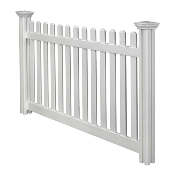
ASSEMBLY INSTRUCTIONS
JIMINY PICKET
VINYL FENCE
Approximate assembly time for one panel
Want to see a video on how to
assemble this product?
WWW.WAMBAMFENCE.COM
WWW.WAMBAMFENCE.COM
(4'H X 7'W)
60 MIN
Scan the QR code
ASSEMBLY
INSTRUCTIONS
VF14300
VF14300
1
VER. 021521
Advertisement

Subscribe to Our Youtube Channel
Related Manuals for WamBam VF14300


Summary of Contents for WamBam VF14300
- Page 1 VF14300 ASSEMBLY INSTRUCTIONS JIMINY PICKET ASSEMBLY INSTRUCTIONS VINYL FENCE VF14300 (4’H X 7’W) 60 MIN Approximate assembly time for one panel Want to see a video on how to assemble this product? Scan the QR code WWW.WAMBAMFENCE.COM WWW.WAMBAMFENCE.COM VER. 021521...
- Page 2 VF14300 ASSEMBLY INSTRUCTIONS GENERAL IMPORTANT INFORMATION Check the inside of the larger pieces in your box for other materials packed inside. When assembling components, place on a non-abrasive surface (i.e. shipping box) to avoid scratching. We recommend an area approximately 5’x 8’ for unobstructed assembling.
- Page 3 We do too! But please, make an exception for this project. We want you to have the best possible ex- perience installing your WamBam Fence and reading the instructions will ensure this. Trust us, you’ll be glad you did! So next time you’re headed to the john, loo, WC, or bathroom, swap out the newspaper for this guide and start reading.
-
Page 4: Practice Makes Perfect
As we all know, time flies when you’re having fun, so expect to spend more than just an afternoon on this project. If you expect to be able to WamBam your fence out in an hour, you’re mistaken. Yeah, we know your dog and kids are running loose and your neighbor is driving you nuts, but if you take your time, your project will be more successful. - Page 5 7. AND FINALLY... Believe Joe, after the past few decades of installing countless fences the WamBam way, the success of your installation is going to depend on three things: 1. Site conditions (And your creativity to work around unforeseen obstacles as they come up, because they are gonna come up!) 2.
- Page 6 VF14300 ASSEMBLY INSTRUCTIONS AVOID THESE PITFALLS! HAVE YOU CONTACTED You must call your local utilities before you start installing your fence to avoid puncturing any unseen underground YOUR LOCAL UTILITIES? utilities, especially electrical or gas lines. Fortunately, this is made easy for you.
- Page 7 Safety Glasses 1ft. Torpedo Level 4ft. Level (optional String Line Level) WamBam Pipe Pounder (Purchase or rent a similar product from Home Depot, Lowe’s or an equipment rental store.) 2in. x 2in. x 6in. Inch Wood “Spacer” Block (2 for each panel)
- Page 8 VF14300 ASSEMBLY INSTRUCTIONS MURPHY’S VINYL FENCE LAWS LET’S PRETEND (JUST FOR A MOMENT) THAT YOU LIVE IN A PERFECT WORLD. To get started, we are going to walk you through how you would install the fence illustrated below. This is the perfect scenario with no curve balls. The ground is level, your fence sections all work out evenly, the birds are chirping, and the sky is blue.
- Page 9 VF14300 ASSEMBLY INSTRUCTIONS DETAILED PRODUCT DIMENSIONS AND SPECIFICATIONS THIS FENCE CAN BE TRIMMED DOWN BOTH IN WIDTH AND HEIGHT TO ACCOMMODATE CUSTOM APPLICATIONS. 88 1/2 in 79 1/2 in 3 in 3 in Ground 3 in 2 in 84 in...
- Page 10 VF14300 ASSEMBLY INSTRUCTIONS LAY OUT MATERIALS STEP 1: Top Rail (1) Picket Cap (13) 1½” x 3½” x 81½” 3½” Self-Drilling Stainless Steel Screw (4) 1¼” Self-Drilling Stainless Steel Screw (4) Picket (13) Vinyl Glue (1) ⅞” x 3” x 42½”...
- Page 11 VF14300 ASSEMBLY INSTRUCTIONS LOCATE AND INSTALL FIRST PIPE ANCHOR STEP 2: STEP 2.1 STEP 2.2 Slide the leveling donut over the Identify the location for the first pipe anchor pipe anchor. positioner. Keep the edge of the anchor posi- tioner 2” away from any vertical surface to leave room for the post.
- Page 12 VF14300 ASSEMBLY INSTRUCTIONS STEP 2.4 STEP 2.5 Drive the pipe anchor 36” At 6” intervals, check that the pipe anchor is into the ground. 24” of the level. Pounding the pipe anchor from all four pipe anchor should be above sides will help to achieve this.
- Page 13 VF14300 ASSEMBLY INSTRUCTIONS INSTALL PIPE ANCHORS STEP 4: STEP 4.1 Lay out one of the rails along the string line. Align the next anchor positioner with the string line and STEP 4.2 the end of the rail. Repeat this step for all of your anchor positioners.
- Page 14 VF14300 ASSEMBLY INSTRUCTIONS REMOVE SOIL AND SECURE ANCHOR POSITIONERS STEP 5: STEP 5.1 (OPTIONAL) If you want your finished fence post to appear buried in the ground, remove about 3” of soil from underneath the anchor positioner. 3” STEP 5.2 STEP 5.3...
- Page 15 VF14300 ASSEMBLY INSTRUCTIONS EXTREME FROST WARNING 1 in. 3 in. Ground Leave a 3” Air Cavity Below the Bottom Ring If you live in the northern U.S or Canada, please leave a minimum 3” air cavity below the bottom plate of the anchor positioner as illustrated above.
- Page 16 VF14300 ASSEMBLY INSTRUCTIONS POSITION AND SECURE LEVELING DONUTS STEP 6: STEP 6.1 Lift the leveling donut to within 1” of the top of the pipe anchor. Adjust the leveling donut as necessary until it is level with the anchor positioner. The leveling donuts should be aligned with the others in the fence line.
- Page 17 VF14300 ASSEMBLY INSTRUCTIONS STEP 7.2 STEP 7.3 Drive a self-drilling tek screw through the post, Repeat step 7 for all anchor positioner, and posts. pipe anchor. Note: Make sure the grooves in the posts are aligned square with your string line.
- Page 18 VF14300 ASSEMBLY INSTRUCTIONS STEP 8.2 Slide the Pickets through the holes in the top and bottom rails. Drive (4) 1¼ Self-Drilling Stainless Steel Screws through the middle of the top and bottom rails and pickets as illustrated. Note: Insert the picket ends with tabs first.
- Page 19 VF14300 ASSEMBLY INSTRUCTIONS SECURE PANELS TO POSTS STEP 10: STEP 10.1 Note: Note: Do not over-tighten the Line up and drive the 3½” Drive a 3½” Self-Drilling Stain- 3½” self-drilling stainless steel self-drilling stainless steel screws less Steel Screw through the...
- Page 20 VF14300 ASSEMBLY INSTRUCTIONS GLUE POST CAPS ONTO POSTS STEP 11: STEP 11.1 STEP 11.2 Put a small bead of vinyl glue along the inside Place the glued post caps on the posts and of the post cap. allow to set for 5-10 minutes.
- Page 21 VF14300 ASSEMBLY INSTRUCTIONS 6935 Reames Rd. Ste. K. Charlotte, NC 28216 hmmm@wambamfence.com 704-892-5222 877-778-5733 WWW.WAMBAMFENCE.COM WWW.WAMBAMFENCE.COM...
Need help?
Do you have a question about the VF14300 and is the answer not in the manual?
Questions and answers