Table of Contents
Advertisement
Service Instructions
GMES9*/GCES9*/AMES9*/ACES9*
O
NLY PERSONNEL THAT HAVE BEEN TRAINED TO INSTALL
(
, "
REPAIR
HEREINAFTER
SERVICE
MANUAL SHOULD SERVICE THE EQUIPMENT
BE RESPONSIBLE FOR ANY INJURY OR PROPERTY DAMAGE ARISING FROM
IMPROPER SERVICE OR SERVICE PROCEDURES
ASSUME RESPONSIBILITY FOR ANY INJURY OR PROPERTY DAMAGE WHICH MAY
. I
,
RESULT
N ADDITION
IN JURISDICTIONS THAT REQUIRE ONE OR MORE
LICENSES TO SERVICE THE EQUIPMENT SPECIFIED IN THIS MANUAL
LICENSED PERSONNEL SHOULD SERVICE THE EQUIPMENT
,
,
INSTALLATION
ADJUSTMENT
SERVICING OR REPAIR OF THE EQUIPMENT
,
SPECIFIED IN THIS MANUAL
OR ATTEMPTING TO INSTALL
REPAIR THE EQUIPMENT SPECIFIED IN THIS MANUAL WITHOUT PROPER
TRAINING MAY RESULT IN PRODUCT DAMAGE
.
INJURY OR DEATH
This manual is to be used by qualified, professionally trained HVAC technicians only. Goodman does not assume any responsibility
for property damage or personal injury due to improper service procedures or services performed by an unqualified person.
The material in this manual does not supercede manufacturer's installation and operation instructions.
is a registered trademark of Maytag Corporation or its related companies and is used under license.
VMES9*/VCES9*
Single Stage Gas Furnaces
and Accessories
,
,
ADJUST
SERVICE OR
")
THE EQUIPMENT SPECIFIED IN THIS
. T
HE MANUFACTURER WILL NOT
. I
F YOU SERVICE THIS UNIT
,
ONLY
. I
MPROPER
,
,
ADJUST
SERVICE OR
,
,
PROPERTY DAMAGE
PERSONAL
Copyright © 2019 Goodman Company, L.P.
,
YOU
All rights reserved.
PROP 65 WARNING
FOR CALIFORNIA CONSUMERS
WARNING
Cancer and Reproductive Harm -
www.P65Warnings.ca.gov
0140M00517-A
RS6612016
April 2019
Advertisement
Chapters
Table of Contents

Related Manuals for Maytag Amana GMES9 Series


Summary of Contents for Maytag Amana GMES9 Series
- Page 1 The material in this manual does not supercede manufacturer's installation and operation instructions. RS6612016 April 2019 is a registered trademark of Maytag Corporation or its related companies and is used under license. All rights reserved. Copyright © 2019 Goodman Company, L.P.
-
Page 2: Table Of Contents
TABLE OF CONTENTS SERVICING TABLE OF CONTENTS ....39 IMPORTANT INFORMATION ......2 - 7 TROUBLESHOOTING ........43 - 44 PRODUCT IDENTIFICATION .......8 - 12 SERVICING ..........45 - 54 INSTALLATION CONSIDERATIONS ..13 - 31 MAINTENANCE ..........55 - 57 SYSTEM OPERATION ........32 - 33 WIRING DIAGRAMS........58 - 59 ACCESSORIES...........34 - 37 IMPORTANT INFORMATION... -
Page 3: Important Information
IMPORTANT INFORMATION To locate an authorized servicer, please consult your telephone book or the dealer from whom you purchased this product. For further assistance, please contact: CONSUMER INFORMATION LINE CONSUMER INFORMATION LINE GOODMAN BRAND PRODUCTS AMANA BRAND PRODUCTS ® ® TOLL FREE TOLL FREE 1-877-254-4729 (U.S. - Page 4 Le monoxyde de carbone peut causer des maladies graves telles que des dommages permanents au cerveau et meme la mort. B10259-216 is a registered trademark of Maytag Corporation or its related companies and is used under license. All rights reserved.
- Page 5 IMPORTANT INFORMATION...
- Page 6 IMPORTANT INFORMATION FOR YOUR SAFETY LIRE AVANT DE METTRE READ BEFORE OPERATING EN MARCHE LIRE AVERTISSEMENT: If you do not follow these instructions WARNING: Quiconque ne respecte pas à exactly, a fire or explosion may result causing property la lettre les instructions dans le presént manuel damage, personal injury or loss of life.
- Page 7 IMPORTANT INFORMATION FOR YOUR SAFETY READ BEFORE OPERATING WARNING: Improper installation, adjustment, If you do not follow these instructions exactly, alteration, service or a fire or explosion may result causing property maintenance can damage, personal injury or loss of life. cause injury or property damage.
-
Page 8: Product Identification
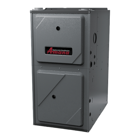
PRODUCT IDENTIFICATION The model and manufacturing number are used for positive identification of component parts used in manufacturing. Please use these numbers when requesting service or parts information. Furnace Nomenclature Brand Minor Revision A- Amana® Brand G- Goodman® A - Ini�al Release V- GMC®... - Page 9 PRODUCT IDENTIFICATION MODEL # MFG # DESCRIPTION GMES920403ANAA GMES920603BNAA Goodman® Brand 92% Single Stage Gas Furnace. 34.5" tall, Upflow/Horizontal GMES920803BNAA Installation, 1-stage gas valve induced draft. PSC motor. 120-volt silicon carbide GMES920804CNAA 17-second hot surface ignition. Left or right gas pipe entry. The furnace also GMES92 GMES920805CNAA features an aluminized steel tubular heat exchanger.
- Page 10 PRODUCT IDENTIFICATION MODEL # MFG # DESCRIPTION AMES920403ANAA AMES920603BNAA ® Amana Brand 92% Single Stage Gas Furnace. Upflow/Horizontal Installation, AMES920803BNAA 34.5" tall, 1-stage gas valve induced draft. PSC motor. 120-volt silicon carbide 17- AMES920804CNAA AMES92 second hot surface ignition. Left or right gas pipe entry. The furnace also features AMES920805CNAA a stainless steel tubular heat exchanger.
- Page 11 PRODUCT IDENTIFICATION MODEL # MFG # DESCRIPTION Fossil Fuel Kit. The AFE18-60A control is designed for use where the indoor coil is located above/downstream of a gas or fossil fuel furnace when used with a heat pump. It will operate with single and two stage heat pumps and single and two stage AFE18-60A furnaces.
- Page 12 PRODUCT IDENTIFICATION MODEL # MFG # DESCRIPTION DCVK-20 (CVENT-2) Concentric Vent Kit. This kit is designed to allow terminations of a direct vent furnace to be "concentrically" vented through a wall or roof. This kit allows a single penetration DCVK-30 to support terminations for both the vent/flue and the combustion air intak (CVENT-3) External Filter Rack Kit.
-
Page 13: Installation Considerations
INSTALLATION CONSIDERATIONS Safety Product Application Please adhere to the following warnings and cautions when This product is designed for use as a residential home gas installing, adjusting, altering, servicing, or operating the furnace. It is not designed or certified for use in mobile home, furnace. - Page 14 INSTALLATION CONSIDERATIONS American National Standards Institute the guidelines given. NOTE: The length of flue and/ or combustion air piping can be a limiting factor in the 25 West 43 Street, 4 Floor location of the furnace. New York, NY 10036 •...
- Page 15 INSTALLATION CONSIDERATIONS • If the furnace is used in connection with a cooling unit, install the furnace upstream or in parallel with the cooling unit coil. Premature heat exchanger failure will result if the cooling unit coil is placed ahead of the furnace.
- Page 16 INSTALLATION CONSIDERATIONS Corrections must be in accordance with the latest edition of Most homes will require outside air be supplied to the fur- the National Fuel Gas Code NFPA 54/ANSI Z223.1 and/or nace area by means of ventilation grilles or ducts connecting CSA B149 Installation Codes.
- Page 17 INSTALLATION CONSIDERATIONS (1) For appliances other than fan-assisted, calculate using the following 9.3.3.1 Two Permanent Openings Method. Two permanent openings, equation: one commencing within 12 in. (300 mm) of the top and one commencing 21 ft within 12 in. (300 mm) of the bottom, of the enclosure shall be provided. Required Volume >...
- Page 18 INSTALLATION CONSIDERATIONS (c) The minimum size of outdoor opening(s) shall be the full size Chimney or Gas Vent of outdoor opening(s) calculated in accordance with 9.3.3, multiplied by the reduction factor. The minimum dimension of air openings shall not be less than 3 in. (80 mm). NOTE: The air duct openings must have a free area of not 9.3.5 Engineered Installations.
- Page 19 INSTALLATION CONSIDERATIONS The 34.5" single stage furnace is one of the products in 9.3.8.5 Ducts shall not be screened where terminating in an attic space. our newly redesigned line of shorter chassis furnaces. It is 9.3.8.6 Horizontal upper combustion air ducts shall not slope downward available in 92% / 96% AFUE up flow / horizontal model and toward the source of combustion air.
- Page 20 INSTALLATION CONSIDERATIONS WARNING DISCHARGE OSSIBLE PROPERTY DAMAGE, PERSONAL INJURY OR DEATH MAY OCCUR IF THE CORRECT CONVERSION KITS ARE NOT INSTALLED. HE APPROPRIATE KITS MUST BE APPLIED TO INSURE SAFE AND PROPER FURNACE OPERATION. Side Side CONVERSIONS MUST BE PERFORMED BY A QUALIFIED INSTALLER OR SERVICE Return Return AGENCY.
- Page 21 INSTALLATION CONSIDERATIONS turers’ recommendations and to verify that all vent/flue piping • A vent termination shall not terminate over public walk- and connectors are compatible with furnace flue products. ways or over an area where condensate or vapor could Additionally, it is the responsibility of the installer to ensure create a nuisance or hazard or could be detrimental that all piping and connections possess adequate structural to the operation of regulators, relief valves, or other...
- Page 22 INSTALLATION CONSIDERATIONS Vent/Flue and Combustion Air Pipe Lengths and Diam- *MES9* / *CES9 Direct Vent (2-Pipe) & Non-Direct Vent (1-Pipe) eters Maximum Allowable Length of Vent/Flue Pipe Refer to the preceding table for applicable length, elbows, (3) (5) Number of Elbow s and pipe diameter for construction of the vent/flue and PIPE MODEL...
- Page 23 INSTALLATION CONSIDERATIONS 90° ELBOWS ELBOWS STRAIGHT 3” - 24” Horizontal vent/flue pipe terminations should be as shown in the following figure. Refer to Vent/Flue Pipe and Combustion Air Pipe - Termination Locations section in this manual or the installation instructions for details concerning location restrictions.
- Page 24 INSTALLATION CONSIDERATIONS 12" MINIMUM VENT/FLUE TEE 90° ELBOW TURNED 9" DOWN 12" Direct Vent Terminal 50,000 Btuh or less 12" 12" Forced Air Inlet 12" MINIMUM ABOVE HIGHEST ANTICIPATED Direct Vent Terminal SNOW LEVEL More than 50,000 Btuh FIGURE 1 2.
- Page 25 INSTALLATION CONSIDERATIONS 1. Determine the best location for the termination kit. Roof termination is preferred since it is less susceptible to damage, has reduced intake contaminants and less visible vent vapors. For side termination, consideration should be given to: a. Possible damage from the vapors to plants/shrubs, other equipment and building materials b.
- Page 26 INSTALLATION CONSIDERATIONS Option 2 The internal vent pipe and elbow may be removed from the furnace to permit the vent to exit the top (original side) of the furnace. If this option is used, an RF000142 Vent-Drain coupling must be used to keep condensate from collecting in the inducer assembly.
- Page 27 INSTALLATION CONSIDERATIONS determined based upon the BTU/ft content of the derated Natural Gas Capacity of Pipe gas and the altitude. Refer to the National Fuel Gas Code, In Cubic Feet of Gas Per Hour (CFH) NFPA 54/ANSI Z223.1, and information provided by the gas Length of Nominal Black Pipe Size supplier to determine the proper orifice size.
- Page 28 INSTALLATION CONSIDERATIONS GAS PIPING CHECKS Complete information regarding tank sizing for vaporiza- tion, recommended regulator settings, and pipe sizing is Before placing unit in operation, leak test the unit and gas available from most regulator manufacturers and propane connections. gas suppliers. Use pipe dope approved for use with L.P.
- Page 29 INSTALLATION CONSIDERATIONS When installing a propane storage tank, the contractor must consider proper tank sizing, safety, efficiency, ground WARNING characteristics and aesthetics. For a residential customer, the size may range from 100-1,000 gallons, depending on F THE INFORMATION IN THESE INSTRUCTIONS IS NOT FOLLOWED EXACTLY, A household use.
- Page 30 INSTALLATION CONSIDERATIONS maintenance. are identified as HUM and EAC. The humidifier and electronic air cleaner neutral terminals are identified as NEUTRAL. All field A 40 V.A. transformer and an integrated electronic control are wiring must conform to applicable codes. Connections should built into the furnace to allow use with most cooling equip- be made as shown.
- Page 31 INSTALLATION CONSIDERATIONS air duct next to the blower compartment. Before installing connections to the furnace may be made with flexible joints the air cleaner, consider the application. The electronic air to reduce noise transmission, if desired. If a central return is cleaner must be readily accessible for periodic inspection used, a connecting duct must be installed between the unit and cleaning of the pre-filters and electronic cells while the...
-
Page 32: System Operation
INSTALLATION CONSIDERATIONS Cooling Mode delay while the induced draft blower is energized to purge the heat exchanger. The ignitor will next be energized and The normal operational sequence in cooling mode is as preheated. The gas valve will then be energized. If flame follows: is not sensed in seven (4) seconds the gas valve will be 1. - Page 33 INSTALLATION CONSIDERATIONS 8. Low Flame Sense Signal. If the furnace continues to 6. Make sure there are no cabinet air leaks allowing sup- operate and the micro-amp signal from the flame sensor ply air to affect combustion falls below specified level, the diagnostic light code for 7.
-
Page 34: Accessories
ACCESSORIES EXTERNAL FILTER RACK ( EFR02 ) SLOTS IN FILTER CLEAR SCREWS EFR02 EXTERNAL FILTER RACK KIT ON UNIT Used on Models 90% Upflow Model Furnaces UNIT SIDE PANEL FRONT OF UNIT LOWER EDGE SCREW SIDE WALL VENT KIT (0170K00000S/0170K00001S) SIDE WALL VENT KIT (0170K00000S) This side wall only vent kit #0170K00000S is to be used with 2”... - Page 35 ACCESSORIES CONCENTRIC VENT CONVERSION KIT (CVENT-2 (DCVK-20) CVENT-3 (DCVK-30) Vent The CVENT-2 (DCVK-20) (2") or the Maintain 12" (18" for Canada) CVENT-3 (DCVK-30) (3") is a con- minimum clearance above highest centric vent kit approved with fur- anticipated snow level. Maximum of 24"...
- Page 36 ACCESSORIES GOODMAN® and AMANA® BRAND *MES9*/*CES9* Model Furance Accessories - 92% Single Stage MODEL NUMBER *MES920403ANAA • • • • • • • • • • • *MES920603BNAA • • • • • • • • • • • *MES920803BNAA •...
- Page 37 ACCESSORIES GOODMAN® and AMANA® BRAND *MES9* Model Furance Accessories - 96% Single Stage MODEL NUMBER *MES960403ANAA • • • • • • • • • • • *MES960603BNAA • • • • • • • • • • • *MES960803BNAA •...
- Page 38 ACCESSORY WIRE DIAGRAMS HIGH VOLTAGE! DISCONNECT ALL POWER BEFORE SERVICING OR INSTALLING THIS UNIT. MULTIPLE POWER SOURCES MAY BE PRESENT. FAILURE TO DO SO MAY CAUSE PROPERTY DAMAGE, PERSONAL INJURY OR DEATH. ALL FUEL SYSTEM CONTROL BOARD - AFE1860A 24VAC +VDC POWER SUPPLY P1-8...
-
Page 39: Servicing Table Of Contents
SERVICING SERVICE NUMBERS CHECKING VOLTAGE ..........................45 CHECKING WIRING ..........................45 S-3A THERMOSTAT AND WIRING .........................45 S-3B HEATING ANTICIPATOR ........................45 CHECKING TRANSFORMER AND CONTROL CIRCUIT ..............46 S-16A CHECKING AIR CIRCULATOR BLOWER MOTOR (PSC) ..............46 S-200 CHECKING DUCT STATIC ........................46 S-201 CHECKING TEMPERATURE RISE ......................47 S-300 CHECKING PRIMARY LIMIT CONTROL ....................47... - Page 40 SERVICING As more and more electronic's are introduced to the Heating INCOMING POWER Trade, Polarization of incoming power and phasing of pri- METER READS METER READS 120 VOLTS 0 VOLTS mary to secondary voltage on transformers becomes more important. Polarization has been apparent in the Appliance industry VOLT / OHM VOLT / OHM since the introduction of the three prong plug, however, the...
- Page 41 SERVICING CUBIC FEET GAS RATE -- CUBIC FEET PER HOUR Seconds Seconds Size of Test Dial Size of Test Dial for One for One Revolutio Revolutio cu/ft cu/ft cu/ft cu/ft cu/ft cu/ft cu/ft cu/ft cu/ft cu/ft 1800 1636 1500 1385 1286 1200 1125...
- Page 42 SERVICING Service Problem No Heat Unsatisfactory Heat POSSIBLE CAUSE Test Method DOTS IN ANALYSIS Remedy GUIDE INDICATE "POSSIBLE CAUSE" • Power Failure Test Voltage • Blown Fuse Test Voltage • Loose Connection Check Wiring • Shorted or Broken Wires Check Wiring S-3A •...
-
Page 43: Troubleshooting
PCBBF145 TROUBLESHOOTING Associated Associated Fault Descrip- Possible Causes Corrective Action Cautions and Symptoms of Abnormal Fault Descrip- Possible Causes tion(s) Notes LED Code Operation LED Code tion(s) • Furnace fails to oper- • No 115 volt power • Manual disconnect NONE •... - Page 44 PCBBF145 TROUBLESHOOTING Fault Descrip- Corrective Action Symptoms of Abnormal Possible Causes Cautions and Associated tion(s) Operation Notes LED Code • Circulator blower runs • Primary or auxiliary • Turn power OFF • Faulty primary or auxiliary • Check primary/auxiliary continuously. No fur- limit circuit is open.
-
Page 45: Servicing
SERVICING cHEcKing tHErmostat, wiring S-1 CHECKING VOLTAGE anD anticiPator WARNING S-3A THERMOSTAT AND WIRING HIGH VOLTAGE ISCONNECT POWER BEFORE SERVICING OR WARNING CHANGING ANY ELECTRICAL WIRING. ULTIPLE POWER SOURCES MAY BE PRESENT. AILURE TO DO SO MAY CAUSE PROPERTY DAMAGE, PERSONAL INJURY OR DEATH. ISCONNECT POWER BEFORE SERVICING. -
Page 46: Checking Transformer And Control Circuit
SERVICING S-16A CHECKING AIR CIRCULATOR BLOWER Cooling Anticipator MOTOR The cooling anticipator is a small heater (resistor) in the ther- mostat. During the "OFF" cycle it heats the bimetal element helping the thermostat call for the next cooling cycle. This WARNING prevents the room temperature from rising too high before the system is restarted. -
Page 47: Checking Temperature Rise
SERVICING 3. Subtract the return air temperature from the supply air temperature to determine the air temperature rise. Allow adequate time for thermometer readings to stabilize. 4. Adjust temperature rise by adjusting the circulator blower speed. Increase blower speed to reduce temperature rise. Decrease blower speed to increase temperature rise. -
Page 48: Checking Flame Rollout Control
SERVICING perature setting and color(s) code. WARNING Manual Reset Auxiliary Limit Located in Blower Deck The 90% single-stage upflow furnaces use two auxiliary limit HIGH VOLTAGE switch for control of high temperatures within the furnace or ISCONNECT POWER BEFORE SERVICING OR CHANGING ANY ELECTRICAL WIRING. -
Page 49: Induced Draft Blower Motor
SERVICING 3. Using a ohmmeter, test for continuity between each To aid in iderntifying these controls, color-coded labels have of the motor leads. been affixed to the back of these controls. Refer to the Rollout 4. Touch one probe of the ohmmeter to the motor Limit Charts in furnace Technical Manual for temperature frame (ground) and the other probe in turn to each settings and color codes. -
Page 50: S-306 Checking Orifices
SERVICING Gas inlet and manifold pressures should be checked and WARNING adjusted in accordance to the type of fuel being consumed. The line pressure supplied to the gas valve must be within ALL G ISCONNECT AS AND LECTRICAL OWER UPPLY. the range specified below. - Page 51 SERVICING Manifold Gas Pressure WARNING Natural Gas 3.5" w.c. HIGH VOLTAGE ISCONNECT ELECTRICAL POWER AND SHUT OFF GAS Propane Gas 10.0" w.c. SUPPLY BEFORE SERVICING OR INSTALLING THIS UNIT. ULTIPLE POWER SOURCES MAY BE PRESENT. AILURE TO DO SO MAY CAUSE PROPERTY DAMAGE, PERSONAL INJURY OR DEATH. The final manifold pressure must not vary more than ±...
-
Page 52: S-308 Checking Hot Surface Ignitor
SERVICING WARNING WARNING HIGH VOLTAGE INE VOLTAGE NOW PRESENT ISCONNECT ELECTRICAL POWER AND SHUT OFF GAS SUPPLY BEFORE SERVICING OR INSTALLING THIS UNIT. 6. Place unit in heating cycle, measure current draw of ignitor ULTIPLE POWER SOURCES MAY BE PRESENT. AILURE TO during preheat cycle. -
Page 53: High Altitude Application (Usa)
SERVICING S-311 HIGH ALTITUDE APPLICATION (USA) WARNING A high altitude kit is required for installationsabove 7,000 ft. Refer to the accessory matrix in this manual to determine INE VOLTAGE NOW PRESENT the proper natural gas and LP gas high altitude kit for your furnace. - Page 54 SERVICING connections, sensor to burner gap, dirty flame sensor, or poor grounding. 6. If absolutely no reading, check for continuity on all com- ponents and if good - replace ignition control module. NOTE: Contaminated fuel or combustion air can create a nearly invisible coating on the flame sensor.
-
Page 55: Maintenance
MAINTENANCE BURNERS WARNING HIGH VOLTAGE LECTRICAL COMPONENTS ARE CONTAINED IN BOTH COMPARTMENTS. O AVOID ELECTRICAL SHOCK, INJURY OR DEATH, DO NOT REMOVE ANY INTERNAL COMPARTMENT COVERS OR ATTEMPT ANY ADJUSTMENT. ONTACT A QUALIFIED SERVICE AGENT AT ONCE IF AN ABNORMAL FLAME APPEARANCE SHOULD DEVELOP. - Page 56 MAINTENANCE HEATING PERFORMANCE TEST The dissipation of the heat transferred to the heat exchang- er is now controlled by the amount of air circulated over its Before attempting to diagnose an operating fault, run a surface. heating performance test and apply the results to the Service Problem Analysis Guide.
- Page 57 MAINTENANCE *MES92 Pressure Switch Trip Points And Usage Chart Coil Cover Coil Cover ID Blower ID Blower ID Blower Set Point on Max Make Set Point on Max Make Coil Cover Model Pressure Fall On Pressure Pressure Fall On Pressure Pressure Switch (PF) W.C.
-
Page 58: Wiring Diagrams
WIRING DIAGRAMS *MES96***/*CES96***A* WITH PCBBF145 CONTROL Wiring is subject to change. Always refer to the wiring diagram on the unit for the most up-to-date wiring. - Page 59 CUSTOMER FEEDBACK We are very interested in all product comments. Please fill out the feedback form on one of the following links: Goodman Brand Products: (http://www.goodmanmfg.com/about/contact-us). ® Amana Brand Products: (http://www.amana-hac.com/about-us/contact-us). ® You can also scan the QR code on the right for the product brand you purchased to be directed to the feedback page.
Need help?
Do you have a question about the Amana GMES9 Series and is the answer not in the manual?
Questions and answers