Table of Contents
Advertisement
Quick Links
Handbook Contents
!
Safety
!
Introduction
!
Quick Start
!
Overview
!
Installation
!
Troubleshooting
!
Accessories
!
Technical Specification
!
Warranty
!
Declaration of Conformity
This symbol is used to alert the user to important
operating or maintenance instructions.
The Lightning bolt triangle is used to alert the user
to the risk of electric shock.
SAFETY:
1. It is important to read these instructions, and to follow them.
2. Keep this instruction manual in an accessible place.
3. Clean only with a dry cloth. Cleaning fluids may effect the equipment.
4. Do not cover or obstruct ventilation of this unit. Install in accordance with the
manufacturer's instructions.
5. Do not install near any heat sources such as radiators, heating vents, or other
apparatus that produces heat.
6. Refer all servicing to qualified personnel. Servicing is required when the
apparatus has been damaged in any way, such as a power supply cord or
plug is damaged, liquid has been spilled or objects have fallen into the
apparatus, the apparatus has been exposed to any rain or moisture, does not
operate normally or has been dropped.
7. WARNING - To reduce risk of fire or electric shock, do not expose this
apparatus to rain or moisture. The apparatus shall not be exposed to dripping
or splashing and no objects filled with liquids, such as vases, shall be placed
on the apparatus.
CAUTION
RISK OF ELECTRIC SHOCK
DO NOT OPEN
ILD100 HANDBOOK
Box Contents
1 x ILD100
1 x Installation & Commissioning
Handbook
1 x Power Cable
TO PREVENT ELECTRIC SHOCK DO NOT
REMOVE THE COVER. THERE ARE NO
USER SERVICEABLE PARTS INSIDE.
REFER SERVICING TO QUALIFIED
PERSONNEL.
Advertisement
Table of Contents

Related Manuals for Ampetronic AMP-ILD100


Summary of Contents for Ampetronic AMP-ILD100
- Page 1 ILD100 HANDBOOK Handbook Contents Box Contents Safety 1 x ILD100 Introduction 1 x Installation & Commissioning Quick Start Handbook Overview 1 x Power Cable Installation Troubleshooting Accessories Technical Specification Warranty Declaration of Conformity This symbol is used to alert the user to important operating or maintenance instructions.
-
Page 2: Quick Start
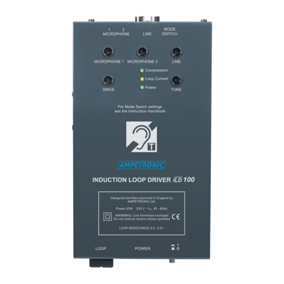
8. Repeat step 6 for the other inputs if used. 9. Listen to the magnetic field produced inside the loop area using a receiving device (e.g Ampetronic ILR3), or examine the performance in more detail with a suitable field strength meter. - Page 3 OVERVIEW MODE LINE SWITCH MICROPHONE MICROPHONE 1 MICROPHONE 2 LINE Š Compression Loop Current Power DRIVE TONE INDUCTION LOOP DRIVER Power 20W 230 V 45 - 65Hz LOOP RESISTANCE 0.2 - 0.8W For mode switch settings see the instruction handbook Designed and Engineered in the UK LOOP POWER...
- Page 4 OVERVIEW cont’d MICROPHONE inputs: 3.5mm mono jack connectors. LINE input: Twin RCA (Phono) connectors, for stereo connection. VOX MODE SWITCH: Switches 1,2 & 3. ILD100 Block diagram...
-
Page 5: Installation
0.8 W " The cable from the loop to the ILD100 output terminals MUST be a twisted pair. If this is longer than 10 metres, contact Ampetronic. Tools & Equipment: " Small hand tools including a wire stripper and a small flat bladed screwdriver. - Page 6 Dynamic microphones cannot normally be used with the equipment, because of the much lower signal level, also the DC bias seriously impairs the performance of the microphone. Ampetronic can supply a special adaptor which permits the use of dynamic microphones (and electrets which are affected by the DC bias).
- Page 7 Listen to the magnetic field produced inside the loop area using a receiving device (e.g Ampetronic ILR3), or examine the performance in more detail with an Ampetronic field strength meter (FSM). From this point onwards, the DRIVE control will not need re-adjusting, as this only affects the peak field strength.
- Page 8 Voice Controlled switching (VOX) There are 3 MODE select switches for the VOX switching features of the ILD100. These switches are located on the top edge of the unit alongside the input connectors. See Overview. The MODE select switches enable their respective functions when in the 'ON' position (the switch is down, towards the base of the unit).The mode select switches may be used in the combinations shown below to achieve the required effect.
-
Page 9: Troubleshooting
TROUBLESHOOTING No power LED: Check that power has been connected to the unit and the POWER is switched on (I/0 button pressed in). Check Mains power connector fuse. Check Mains power is available at the socket. No Compression LED: Check that a microphone or signal source is connected and the corresponding input control has been set. - Page 10 3-wire balanced circuits & keep away from loop cables. See also point 1 of Instability. ACCESSORIES Details of all products & services provided by Ampetronic can be found at www.ampetronic.com Desktop Microphone EM195A, or Boundary Microphone Q400, or Tieclip style Microphone EM336, are available if required.
-
Page 11: Technical Specifications
Assessories. Compression (AGC): >36dB dynamic range. Standards: Controlled by adjusting input level. Meets relevant CE, EMC and safety standards. Loop Design: Depends on application, see Please contact Ampetronic if you Designing induction loops need further assistance. handbook or consult Ampetronic. -
Page 12: Warranty
WARRANTY This product carries a five year parts and labour warranty from date of shipment from Ampetronic. To qualify for the five year warranty, the product must be registered at www.ampetronic.com (products/warranty), without which the warranty will be valid for two years only.
Need help?
Do you have a question about the AMP-ILD100 and is the answer not in the manual?
Questions and answers