Table of Contents
Advertisement
Quick Links
Handbook Contents
Safety
Introduction
Quick Start
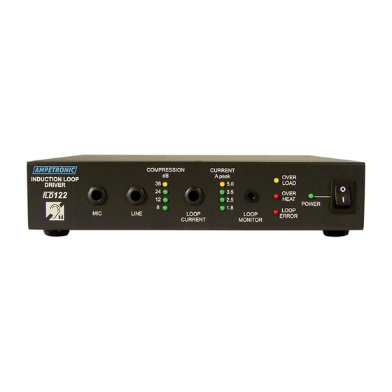
Overview
Installation
Troubleshooting
Accessories
Technical Specification
Warranty
Declaration of Conformity
This symbol is used to alert the user to important
operating or maintenance instructions.
The Lightning bolt triangle is used to alert the user
to the risk of electric shock.
SAFETY
1. It is important to read these instructions, and to follow them.
2. Keep this instruction manual in an accessible place.
3. Clean only with a dry cloth. Cleaning fluids may effect the equipment.
4. Do not block any ventilation openings. Install in accordance with the
manufacturer's instructions.
5. Do not install near any heat sources such as radiators, heating vents, or other
apparatus that produces heat.
6. WARNING - THIS APPARATUS MUST BE EARTHED / GROUNDED.
7. Only power cords with the correct power connector may be used to maintain
safety. Cables incorporating the UK 13A fused plug, Schuko with earthing
contacts or UL approved "grounding type" are acceptable. These must be
plugged into power outlets which provide a protective earth.
8. Refer all servicing to qualified personnel. Servicing is required when the
apparatus has been damaged in any way, such as a power supply cord or
plug is damaged, liquid has been spilled or objects have fallen into the
apparatus, the apparatus has been exposed to any rain or moisture, does not
operate normally or has been dropped.
9. WARNING - To reduce risk of fire or electric shock, do not expose this
apparatus to rain or moisture. The apparatus shall not be exposed to dripping
or splashing and no objects filled with liquids, such as vases, shall be placed
on the apparatus.
CAUTION
RISK OF ELECTRIC SHOCK
DO NOT OPEN
.
ILD122 HANDBOOK
Box Contents
1 x ILD122
1 x Loop connector
1 x Installation & Commissioning
Handbook
1 x Power Cable
TO PREVENT ELECTRIC SHOCK DO NOT
REMOVE THE COVER. THERE ARE NO
USER SERVICEABLE PARTS INSIDE.
REFER SERVICING TO QUALIFIED
PERSONNEL.
Advertisement
Table of Contents

Related Manuals for Ampetronic ILD122


Summary of Contents for Ampetronic ILD122
- Page 1 ILD122 HANDBOOK Handbook Contents Box Contents Safety 1 x ILD122 Introduction 1 x Loop connector Quick Start 1 x Installation & Commissioning Overview Handbook Installation 1 x Power Cable Troubleshooting Accessories Technical Specification Warranty Declaration of Conformity This symbol is used to alert the user to important operating or maintenance instructions.
-
Page 2: Quick Start
INTRODUCTION The ILD122 Induction Loop Driver has been designed as a high quality amplifier for use with conference rooms, stadia, theatres, sports halls, confidential rooms, lecture halls and cinemas. Depending on a number of factors regarding the installation of the loop and set-up of the amplifier, the ILD122 can provide compliance with IEC60118-4 for areas >... - Page 3 OVERVIEW...
- Page 4 Connections LINE RING SOURCE INPUT SLEEVE + (Signal hot) Balanced - (Signal cold) Connection of 3-pole Plug TO ILD122 with balanced signals. LINE INPUT Use Twin-screened cable. RING SLEEVE SOURCE Unbalanced + (Signal) TO ILD122 Connection of 3-pole plug. Use Twin-screened cable.
-
Page 5: Installation
Block Diagram +15V Phantom Power Compression LEDs Switch Overheat Gain Boost Microphone Loop Overload Current LEDs Input Error Microphone Gain Compressor Output Line Loop Loop Input Metal Slave Output Current Loss Correction Line Loop Gain Monitor Power Power Switch 150mA +15V Power 230V... - Page 6 Ampetronic signal processing equipment, or for obtaining a signal for recording. See Connections section for details. 4.Connect AC power to the ILD122. See points 6 and 7 in Safety section. 5. Switch ON. The POWER LED will flash for a few seconds while an internal self test is performed and the loop resistance is tested.
- Page 7 Once the LOOP CURRENT AND METAL LOSS CORRECTION have been adjusted to the correct level they should not need re-adjusting. 9. If not already done so, steps can now be taken to integrate the ILD122 into a PA / mixer arrangement following standard audio techniques. If any unusual effects are experienced refer to the troubleshooting section.
-
Page 8: Troubleshooting
Switch the unit OFF, remove all connections except the loop and power connections, turn all front panel controls to minimum and switch back ON. If the problem persists, contact Ampetronic for advice. COMPRESSION LEDs not illuminating: Check input connections. - Page 9 Due to insufficient LOOP CURRENT or excessive metal loss. May require a special loop design to achieve acceptable performance, contact Ampetronic for advice. Instability or high frequency noise 1) It is possible for the loop cable to become grounded under fault conditions, resulting in instability which may sound like high frequency noise, buzz or whistling.
- Page 10 Wall mount brackets are available for mounting the amplifier on the wall with appropriate fixings. A 1U rack mount tray is available which can be used to mount up to two ILD122’s. Blanking plates can be used to cover unused sections.
-
Page 11: Technical Specifications
½ rack width, 1U high. Compression (AGC): Standards: >36dB dynamic range Meets relevant CE, EMC and Controlled by adjusting input level. safety standards. Loop Design: Depends on application, see Please contact Ampetronic if you need Designing induction loops handbook further assistance. or consult Ampetronic. -
Page 12: Warranty
The five year warranty is dated from the time the equipment leaves Ampetronic and NOT when it is installed. DECLARATION OF CONFORMITY Manufacturer: Ampetronic Ltd.
Need help?
Do you have a question about the ILD122 and is the answer not in the manual?
Questions and answers