Table of Contents
Advertisement
Quick Links
Handbook Contents
•
Safety
•
Introduction
•
Quick Start
•
Overview
•
Installation
•
Troubleshooting
•
Accessories
•
Technical Specification
•
Warranty
•
Declaration of Conformity
-4-
This symbol is used to alert the user to important
ill
operating or maintenance instructions.
/,\
The Lightning bolt triangle is used to alert the user
ill
to the risk of electric shock.
SAFETY
1. It is important to read these instructions, and to follow them.
2. Keep this instruction manual in an accessible place.
3. Clean only with a dry cloth. Cleaning fluids may effect the equipment.
4. Do not block any ventilation openings. Install in accordance with the
manufacturer's instructions.
5. Do not install near any heat sources such as radiators, heating vents, or other
apparatus that produces heat.
6. WARNING - THIS APPARATUS MUST BE EARTHED/ GROUNDED.
7. Only power cords with the correct power connector may be used to maintain
safety. Cables incorporating the UK 13A fused plug, Schuko with earthing
contacts and UL approved "grounding type" are acceptable. These must be
plugged into power outlets which provide a protective earth.
8. Refer all servicing to qualified personnel. Servicing is required when the
apparatus has been damaged in any way, such as a power supply cord or
plug is damaged, liquid has been spilled or objects have fallen into the
apparatus, the apparatus has been exposed to any rain or moisture, does not
operate normally or has been dropped.
9. WARNING To reduce risk of fire or electric shock, do not expose this
apparatus to rain or moisture. The apparatus shall not be exposed to dripping
or splashing and no objects filled with liquids, such as vases, shall be placed
on the apparatus.
ILD500 HANDBOOK
Box Contents
1 x ILD500
1 x Loop connector
1 x Installation & Commissioning
Handbook
2 x 1 U Rack mounting ears
1 x Power Cable
TO PREVENT ELECTRIC SHOCK DO NOT
REMOVE THE COVER. THERE ARE NO
USER SERVICEABLE PARTS INSIDE.
REFER SERVICING TO QUALIFIED
PERSONNEL.
Advertisement
Table of Contents

Subscribe to Our Youtube Channel
Related Manuals for Ampetronic ILD500


Summary of Contents for Ampetronic ILD500
- Page 1 ILD500 HANDBOOK Handbook Contents Box Contents • Safety 1 x ILD500 • Introduction 1 x Loop connector • Quick Start 1 x Installation & Commissioning • Overview Handbook • Installation 2 x 1 U Rack mounting ears • Troubleshooting 1 x Power Cable •...
-
Page 2: Quick Start
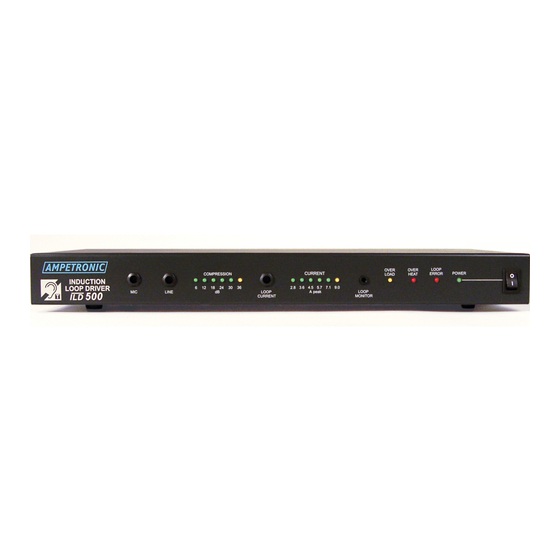
9. Repeat step 6 for the other input if used. 1 a.Listen to the magnetic field produced inside the loop area using a receiving device (e.g Ampetronic ILR3), or examine the performance in more detail with a field strength meter. - Page 3 LOOP LOOP LINE A peak ¢ ILD500 ¢ CURRENT MONITOR CJCJCJ rel] INDUCTION LOOP DRIVER ILD500 G·�o , c� CJCJCJ ��1�; '"v IA� Ji. =�=.�u ill'-""""""'---'m 0 CJCJCJ 0 CJCJCJ CJCJCJ DesignedandEnQinooredinlhoUK MIC and LINE: Screwdriver adjustable controls which set the AC POWER: Standard 3-pole IEC320 connector containing level of signal fed into the compressor from Mic and Line inputs.
- Page 4 Connections LINE INPUT Unbalanced Connection of 3-pole plug. Use Twin-screened cable. Must be 3m or less. �---- - Screen �---- - (Signal cold) INPUT --r-----�--- + (Signal hot) Connection of balanced male XLR for microphone input SLAVE RECORDING DEVICE LOOP CONNECTOR use either NL4 connections 1or 2, or both as required Internal unit connections...
- Page 5 Block Diagram +15V ��!: �j Compression LEDs Switch Overheat Gain Boost Overload Slave Correction Power ±15V Power Switch 150mA +15V 230V -15V 120V Output AC Power -----.--"'---+------� av Socket +15V -15V Use cable supplied. Must be 3m or less. INSTALLATION Location: The unit may be free standing or 19"...
-
Page 6: System Requirements
CD player, which is not connected into any other system. This avoids the complication of ground loops and feedback etc, whilst the unit is set up. The f o llowing procedure describes the installation of a stand alone ILD500, and does not incorporate connection of other ancillary units such as microphone pre-amps or signal processing units. - Page 7 9. If not already done so, steps can now be taken to integrate the ILD500 into a PA / mixer arrangement f o llowing standard audio techniques. If any unusual effects are experienced refer to the troubleshooting section.
-
Page 8: Troubleshooting
Switch the unit OFF, remove all connections except the loop and power connections, turn all front panel controls to minimum and switch back ON. If the problem persists, contact Ampetronic f o r advice. COMPRESSION LEDs not illuminating: Check input connections. - Page 9 Due to insufficient LOOP CURRENT or excessive metal loss. May require a special loop design to achieve acceptable performance, contact Ampetronic f o r advice. Instability or high frequency noise 1) It is possible f o r the loop cable to become grounded under fault conditions, resulting in instability which may sound like high frequency noise, buzz or whistling.
- Page 10 If the fuse fails again, return the unit to Ampetronic for evaluation it may well be covered under warranty, which will be invalidated by removing the cover. If the fuse does not fail a 'loop error' may be indicated, but shows that the unit is working correctly.
-
Page 11: Technical Specifications
19" rack width, 1 U high. Controlled by adjusting input level. Standards: Loop Design: Meets relevant CE, EMC and Depends on application, see safety standards. Designing induction loops handbook or consult Ampetronic. Please contact Ampetronic if you need further assistance. -
Page 12: Warranty
ACCESSORIES Details of all products and services provided by Ampetronic can be f o und at www.ampetronic.co Wall mount brackets are available for mounting the amplifier on the wall with appropriate fixings. Microphone pre-amplifiers f o r 1, 2 or 5 microphones, as well as other line level signals.
Need help?
Do you have a question about the ILD500 and is the answer not in the manual?
Questions and answers
why does not the Download function? Im trying to download the Ampetronic ILD500 Handbook