Chicago Electric DEMOLITION HAMMER 93853 Set Up And Operating Instructions Manual
Chicago electric power hammer user manual
Hide thumbs
Also See for DEMOLITION HAMMER 93853:
- Assembly and operating instructions manual (19 pages)
Table of Contents
Advertisement
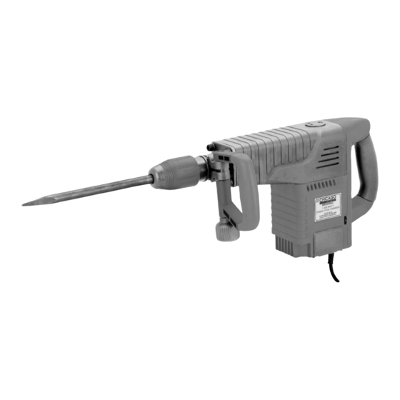
DEMOLITION HAMMER
SET up AND OpERATINg INSTRucTIONS
Visit our website at: http://www.harborfreight.com
Read this material before using this product.
Failure to do so can result in serious injury.
SAVE THIS MANuAL.
Copyright
2006 by Harbor Freight Tools
©
contained herein may be reproduced in any shape or form without the express written consent of Harbor
Freight Tools. Diagrams within this manual may not be drawn proportionally. Due to continuing improve-
ments, actual product may differ slightly from the product described herein. Tools required for assembly
and service may not be included.
For technical questions or replacement parts, please call 1-800-444-3353.
Revised Manual 10d
Model
93853
. All rights reserved. No portion of this manual or any artwork
®
Advertisement
Table of Contents

Related Manuals for Chicago Electric DEMOLITION HAMMER 93853


Summary of Contents for Chicago Electric DEMOLITION HAMMER 93853
- Page 1 DEMOLITION HAMMER SET up AND OpERATINg INSTRucTIONS Visit our website at: http://www.harborfreight.com Read this material before using this product. Failure to do so can result in serious injury. SAVE THIS MANuAL. Copyright 2006 by Harbor Freight Tools © contained herein may be reproduced in any shape or form without the express written consent of Harbor Freight Tools.
-
Page 2: Specifications
Electrical Requirements Blows Per Minute Variable Speed Settings Handle Types Included Chisels Chisel Shank Size Chisel Retainer Note: SDS and SDS MAX chisels (both not included) can be used with this Demolition Hammer. You will need this manual for the safety warnings and precautions, assembly, operating, inspection, maintenance and cleaning procedures, parts list and assembly diagram. -
Page 3: Electrical Safety
grounded tools must be plugged into an outlet properly installed and grounded in accordance with all codes and ordinances. Never remove the grounding prong or modify the plug in any way. Do not use any adapter plugs. Check with a qualified electrician if you are in doubt as to whether the outlet is properly grounded. - Page 4 Remove adjusting keys or wrenches before turning the power tool on. wrench or a key that is left attached to a rotating part of the power tool may result in personal injury. Do not overreach. Keep proper footing and balance at all times. footing and balance enables better control of the power tool in unexpected situations.
-
Page 5: Specific Safety Rules
Tool service must be performed only by qualified repair personnel. or maintenance performed by unqualified personnel could result in a risk of injury. When servicing a tool, use only identical replacement parts. Follow instructions in the “Inspection, Maintenance, And Cleaning” section of this manual. - Page 6 Do not drill or break into existing walls, floors, or other blind areas where electrical wiring may exist. If this situation is unavoidable, disconnect all fuses or circuit breakers feeding the worksite. use a metal detector to determine if there are gas or water pipes hidden in the work area or call the local utility company for assistance before beginning the operation.
- Page 7 these chemicals are: lead from lead-based paints, crystalline silica from bricks and cement or other masonry products, arsenic and chromium from chemically treated lumber. Your risk from these exposures varies, depending on how often you do this type of work. To reduce your exposure to these chemicals: work in a well ventilated area, and work with approved safety equipment, such as those dust masks that are specially designed to filter out microscopic particles.
-
Page 8: Vibration Hazard
This tool vibrates during use. Repeated or long-term exposure to vibration may cause temporary or permanent physical injury, particularly to the hands, arms and shoulders. To reduce the risk of vibration-related injury: Anyone using vibrating tools regularly or for an extended period should first be examined by a doctor and then have regular medical check-ups to ensure medical problems are not being caused or worsened from use. -
Page 9: Grounding
Improperly connecting the grounding wire can result in WARNINg electric shock. Check with a qualified electrician if you are in doubt as to whether the outlet is properly grounded. Do not modify the power cord plug provided with the tool. Never remove the grounding prong from the plug. -
Page 10: Extension Cords
with the applicable standards of Underwriters Laboratories, Inc., the Canadian Standard Association, and the National Electrical Code. (See Outlets for 2-prong plug.) Double insulated tools may be used in either of the 120 volt outlets shown in the preceding illustration. (See Outlets for 2-prong plug.) Grounded tools require a three wire extension cord. - Page 11 REcOMMENDED MINIMuM WIRE gAugE FOR EXTENSION cORDS* NAMEpLATE AMpERES (at full load) 25 Feet 0 – 2.0 2.1 – 3.4 3.5 – 5.0 5.1 – 7.0 7.1 – 12.0 12.1 – 16.0 16.1 – 20.0 TABLE A * Based on limiting the line voltage drop to five volts at 150% of the rated amperes. Double Insulated Canadian Standards Association Underwriters Laboratories, Inc.
-
Page 12: Product Features
When unpacking, check to make sure all the parts shown on the parts List on page 16 are included. If any parts are missing or broken, please call Harbor Freight Tools at the number shown on the cover of this manual as soon as possible. Note: For additional information regarding the parts listed in the following pages, refer to the Assembly Diagrams on page 17. -
Page 13: Operating Instructions
Variable Speed control (72): Variable Speed Control Dial. The impact rate (BPM) and rotating speed (RPM) can be varied according to the type of work being performed by setting the Variable Speed Control Dial to the selected setting: 1-2-3-4-5-6 (“1” Being the lowest. -
Page 14: Inspection, Maintenance, And Cleaning
Grasp the Demolition Hammer firmly by its rear Handle (62) and Auxiliary Handle (104A). Then, turn the Power Switch (66) to its “ON” position to begin work. IMpORTANT: This Demolition Hammer requires a short period of time to warm up. Depending on the room temperature, this time may vary from approximately 15 seconds (at 90 degrees Fahrenheit) to 2 minutes (at 32 degrees Fahrenheit). - Page 15 are worn down, replace both Carbon Brushes. If, however, the Carbon Brushes are just dirty they may be cleaned by rubbing them with a pencil eraser. If cleaning and replacing used brushes, try to install them in the same holders and in the same direction they were removed.
-
Page 16: Troubleshooting
problem Chisel installs with difficulty. Tool does not run. Tool does not stop. Poor cutting efficiency. Tool overheats and suddenly stops running. pLEASE READ THE FOLLOWINg cAREFuLLY THE MANUFACTURER AND/OR DISTRIBUTOR HAS PROVIDED THE PARTS LIST AND ASSEMBLY DIAGRAM IN THIS MANUAL AS A REFERENCE TOOL ONLY. -
Page 17: Parts List
* cannot be ordered individually. Must be ordered as a complete Motor Assembly. Includes parts 33, 34, 35, 36, 37, 40, 58, 59, 60, 61, 73, 74. ** cannot be ordered individually. Must be ordered as a complete carbon Brush Assembly. Includes parts 75, 76, 77. -
Page 18: Assembly Diagram
Note: Some parts are listed and shown for illustration purposes only, and are not available individually as replacement parts. SKU 93853 For technical questions, please call 1-800-444-3353 ASSEMBLY DIAgRAM REV 08g, 10d PAGE 18... -
Page 19: Limited 1 Year / 90 Day Warranty
LIMITED 1 YEAR / 90 DAY WARRANTY Harbor Freight Tools Co. makes every effort to assure that its products meet high quality and durability standards, and warrants to the original purchaser that for a period of ninety days from date of purchase that the engine/motor, the belts (if so equipped), and the blades (if so equipped) are free of defects in materials and workmanship.
Need help?
Do you have a question about the DEMOLITION HAMMER 93853 and is the answer not in the manual?
Questions and answers