Table of Contents
Advertisement
Quick Links
Electrical and electronic equipment and batteries
should be recycled at a facility capable of handling
these items. Contact your local authority for details
of disposal rules.
Manufacture:
ALINCO, INC.
Y odoyabashi Dai-bldg 13F
4-4-9 Koraibashi, Chuo-ku, Osaka 541-0043 Japan
Phone: +81-6-7636-2362 Fax: +81-6-6208-3802
http://www.alinco.com
E-mail:export@alinco.co.jp
Copyright Alinco, lnc. PS1001A / FNFN-EE
Printed in China
Advertisement
Table of Contents

Subscribe to Our Youtube Channel
Related Manuals for Alinco DR-MD520T


Summary of Contents for Alinco DR-MD520T
- Page 1 Phone: +81-6-7636-2362 Fax: +81-6-6208-3802 http://www.alinco.com E-mail:export@alinco.co.jp Electrical and electronic equipment and batteries should be recycled at a facility capable of handling Copyright Alinco, lnc. PS1001A / FNFN-EE these items. Contact your local authority for details of disposal rules. Printed in China...
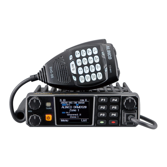
- Page 2 VHF/UHF FM Digital Transceiver DR-MD520T/E Instruction Manual Thank you for purchasing your new Alinco transceiver. Please read this manual carefully before using the product to ensure full performance, and keep this manual for future reference as it contains information on after-sales services. In case addendum or errata...
- Page 3 No part of this document may be reproduced, translated or transcribed during lightning. in any from or by any means without the prior permission of Alinco. Inc., Enclosure protection Osaka, Japan. Alinco and ALINCO logo are registered trademarks of ■...
- Page 4 Comformity information this manual may be updated without any notice or obligation. Alinco cannot be liable for pictorial or typographical inaccuracies. Changes Manufacturer: or modifications not expressly approved by the party responsible for ALINCO, Inc. Electronics Division compliance could void the user's authority to operate the equipment Yodoyabashi Dai-bldg.
- Page 5 ■ This equipment has been tested and found to comply with the limits for a This Alinco transceiver has been tested and complies with the Class B digital device, pursuant to Part 15 of the FCC Rules. standards listed below, in regards to Radio Frequency (RF) energy and These limits are designed to provide reasonable protection against electromagnetic energy (EME) generated by the transceiver.
- Page 6 • This transceiver is NOT ATEX approved and NOT intended for the use • Use only Alinco authorized accessories The use of other than in hazardous explosive atmospheres. recommended or approved body- worn accessories may result in RF exposure levels which exceed the FCC's occupational/ controlled...
- Page 7 WARNING To prevent any hazard during operation of Alinco’s radio product, in this Do not use this product in close proximity to other electronics manual and on the product you may find symbols shown below. Please devices, especially medical ones. It may cause interference read and understand the meanings of these symbols before starting to to those devices.
- Page 8 WARNING Handling this product: Do not plug the power-supply into the wall outlet if the contacts are dirty and/or dusty. Be sure to reduce the audio output level to minimum before Short circuiting and/or overheating may result in fire, electric using a headset.
- Page 9 WARNING About power-supply CAUTION Use only reliable power supply of specific DC output range and Environment and condition of use: be mindful of the polarity of the cables and DC jack. Do not use the product in proximity to a TV or a radio. It may Always turn off the power supply when connecting or cause interference or receive interference.
-
Page 10: Table Of Contents
CONTENTS Recieving ..................11 Supplied Accessories ............1 Transmitting ..................11 Supplied Accessories ............... 1 New Channel ................... 12 Initial Installation ..............2 Delete Channel ................12 Mobile Installation ................2 Receiving and Responding to a Radio Call ........12 Taken Off Mobile From Car .............. 2 Make a Digital Call ................ -
Page 11: Supplied Accessories
The standard accessories may vary slightly depending on the version you have purchased. Please contact your local authorized Alinco dealer should you have any questions. Alinco and authorized dealers are not responsible for any typographical errors there may be in this manual. Standard accessories may change without notice. -
Page 12: Initial Installation
Initial Installation Mobile installation The transceiver may be installed in any position in your car, where the Determine the appropriate controls and microphone are easily accessible and it does not interfere with angle of the transceiver, using the safe operation of the vehicle. If your vehicle is equipped with air bags, the 3 screw hole positions be certain your transceiver will not interfere with their deployment. -
Page 13: Dc Power Cable Connection
Initial Installation Reconnect any wiring removed from the negative terminal. DC Power Cable Connection Mobile Operation The vehicle battery must have a nominal rating of 12V. Never connect the transceiver to a 24V battery. Be sure to use a 12V vehicle battery that has sufficient current capacity. -
Page 14: Antenna Connection
Initial Installation The current capacity of your power supply must be 12A or more. the problem is resolved, replace the fuse. If newly installed fuses continue to blow, disconnect the power cable and contact your dealer for Connect the DC power cable to the regulated DC power supply and assistance. -
Page 15: Accessories Connections
Initial Installation SPEAKER MIC Transmitting without first connecting an antenna or other matched For voice communications, connect a provided Speaker mic into the load may damage the transceiver. Always connect the antenna to the transceiver before transmitting. socket on the front of the main unit. Turn the ring firmly on the plug All fixed stations should be equipped with a lightning arrester to reduce until it locks. -
Page 16: Getting Acquainted
Getting Acquainted Front panel Press : Press to return to previous menus. Press to delete characters when texting message. EXIT key Press and hold to active keypad lock. Press/ press and hold these keys to use the pre- P1-P6 key programmed functions. -
Page 17: Programmed Key
Getting Acquainted Programmed Key GPS Info Check the GPS position information It is possible to set different functions for [P1], [P2], [P3],[P4],[P5],[P6]. Monitor Monitor the weak signal or the signal with unmatched ID. A,B,C,D. Main CH Choose channel A or channel B as the main channel Method 1: In radio Menu - Settings - Radio Set - P1~P6, PA-PD. -
Page 18: Hot Key Setting For P1,P2,P3,P4,P5,P6, Pa-Pd
Getting Acquainted In standby, if the call contact type for a channel is "Single call" , Should edit the analog quick call first, then choose analog Analog in the hot key set. Press the key to transmit 2Tone/5Tone/ press the key programmed as " Channel Ranging" to turn on this CH Ranging DTMF to start the analog quick call. -
Page 19: Speaker Mic
Getting Acquainted SPEAKER MIC NO. KEY FUNCTION Switches between Main and Sub bands. Number Key Input VFO frequency or DTMF dial out etc. Programmed key [Set the programs in PC software]. PA MENU The MENU key is set as default setting. Programmed key [Set the programs in PC software]. -
Page 20: Microphone Operation
Microphone Operation MICROPHONE OPERAtION RESUME FACtORY DEFAULt If your transceiver seems to be malfunctioning becuase of wrong DOWN operation or setup, this function will be able to resume all setup and channels to factory default. Press and hold [P2] Key + CH knob + Power key at the same time to power on the transceiver. -
Page 21: Basic Operations
Basic Operations tURNING ON tHE POwER Select a Channel Turn on the transceiver by pressing the power key, and the LCD displays Press the programmed [VFO/MR] key to switch the radio between VFO "Booting, please wait". Then it will show a start-up message, and you will and Channel mode, select Channel mode. -
Page 22: New Channel
Basic Operations New channel Choose a programmed channel. Press [EXIT] key to enter the TG List, turn the channel switch or press Enter radio Menu-Settings-Chan Set-New Chan. the UP/DN key on microphone to choose a TG/DMR ID. Input the channel number and name. Method 2: Select a temporary TG/DMR ID from the keypad. -
Page 23: Advanced Features For Private Call
Advanced Features for Private Call Kill Access Advanced Features for Private Call Select Kill, and it will send out a kill signaling to the target radio which Method 1: To Access a Private Call from Contact list will be killed (No display, no operation) when receiving the signaling and a. -
Page 24: Main Menu Functions
MAIN MENU FUNCTIONS talk Group Zone TG List: Will display the talk group list which had been programmed in 1. Select a Zone the PC software. This list is used as a look-up table to display the contact A Zone is a group of channels grouped together. The radio has 250 TG information when receiving a call. -
Page 25: Settings
MAIN MENU FUNCTIONS Roaming Zone OutRange Note Select Roam Zone: select a Roaming Zone from the list to set it as When the repeater is out of range after the repeater check, the radio will active zone. You can also scroll down the list of Zones and select Add remind out of range. - Page 26 MAIN MENU FUNCTIONS name, and then the programmed VFO/ MR key is not valid. It will allow you set up the audio pitch. Frequency: The radio will work in VFO mode and display the frequency, Normal: Low pitch,for TX audio only. which allows the programmed VFO/MR key to switch the VFO and Enhance: High pitch,for TX audio only.
- Page 27 MAIN MENU FUNCTIONS CH Color A (17) Hold pressing PTT key, at the same time press UP or DN key on microphone to transmit the TBST tone. Set color for the band A channel display. Scan Mode CH Color B (18) (28) Set color for the band B channel display.
- Page 28 MAIN MENU FUNCTIONS The password shall be set up in CPS-Optional Setting-Power on-Power- Radio must also be in Double Slot operation. on Password Char. ** Please Turn Off Digital Monitor when using the Cross-band repeat AuRepeater A or B (For VFO A or B) function** (34-35) Turn on the Auto Repeater function, the TX frequency in VFO mode will...
- Page 29 MAIN MENU FUNCTIONS M-SMS: Allows SMS text communication with Motorola DMR radio. Delete Chan H-SMS: Allows SMS text communication with Hytera DMR radio. Allows to delete current channel. CTC ste (62) a. Select "Delete Chan",the radio will remind " Delete? " Squelch Tail Eliminate(STE) setting with CTCSS.
- Page 30 MAIN MENU FUNCTIONS Name (10) the channel. Allow reset the channel name, this function is only valid in channel Select Cur List: Select the current RX Group List. Add Group: Add a TG mode. to the current RX Group List. TX Allow (11) Remove Group: Remove a TG from the current RX Group List.
- Page 31 MAIN MENU FUNCTIONS Tx Interrupt (22) C&T: You can hear the call when receives a matched CTCSS/DCS and matched signaling. This feature allows the supervisor to start the transmission while another person is talking. It allows supervisor to override the ongoing C|T: You can hear the call when receives a matched CTCSS/DCS or.
-
Page 32: Record
MAIN MENU FUNCTIONS 2Tone Enc/Dec (23-24) Record Set a 2Tone as the default call ID for the current channel. Press the [PTT] The voice record is designed for security use purpose. Each call will key to transmit the selected 2Tone. be saved as a separated recording file with DMR ID and time details. -
Page 33: Gps Positioning Function
MAIN MENU FUNCTIONS APRS Location Reporting GPS Positioning Function APRS menu is not in menu list when GPS is off, you have to turn on 1. GPS On/Off GPS first if you want to use APRS menu. Turn the GPS on or off manually. Upload Type 2. -
Page 34: Digital Monitor
MAIN MENU FUNCTIONS ● Slot 2: Use slot 2 Digital Monitor Upload ID: Allow user to set an APRS TG as the destination. DigiMoni Switch Digi APRS Info off: Turn off Digital Monitor The received APRS information will be saved in radio for look back use. Single Slot: Monitor the current TS Click on "Digi APRS Info"... -
Page 35: Reset
RESET A. Power off the radio. B. Then power it on while holding the [P2] and the channel switch at the same time. C. The radio will start up with a note on the display – "Are you sure you want to initialize radio?"... -
Page 36: Specifications
RX: 136MHz~174MHz, 220MHz~225MHz, 400MHz~480MHz 222~225MHz:5W(High)/1.5W(middle low small) RF Power Output Frequency Range TX: 144MHz~148MHz, 222MHz~225MHz, UHF: 40W/25W/10W/1W 420MHz~450MHz (DR-MD520T) Less than 1GHz: -36dBm FM: 88MHz~108MHz Channel Spacing More than 1GHz: -30dBm RX : 136Mhz~174MHz, 400Mhz~480MHz Frequency Range TX : 144MHz~146Mhz, 430MHz~440MHz 25kHz: 40dB FM Hum &... - Page 37 10 0 WARNING ■ FCC Compliance Statements: ■Licensing Information This device complies with part 15 of the FCC Rules. Use our radio in USA is subject to the rules & regulations of FCC. Changes or Operation is subject to the following two conditions: modifications not expressly approved by our may void the user authority granted by (1) This device may not cause harmful interference, and the FCC to operate this radio and should not be made.
Need help?
Do you have a question about the DR-MD520T and is the answer not in the manual?
Questions and answers