Table of Contents
Advertisement
Quick Links
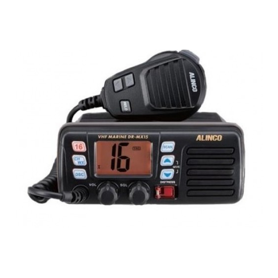
VHF Marine Transceiver
DR-MX15
Instruction Manual
Thank you for purchasing your new Alinco transceiver.
Please read this manual carefully before using the
product to ensure full performance, and keep this
manual for future reference as it contains information
on after-sales services. In case addendum or errata
sheets are included with this product, please read
those materials and keep them together with this
instruction manual for future reference.
Advertisement
Table of Contents

Subscribe to Our Youtube Channel
Related Manuals for Alinco DR-MX15


Summary of Contents for Alinco DR-MX15
- Page 1 VHF Marine Transceiver DR-MX15 Instruction Manual Thank you for purchasing your new Alinco transceiver. Please read this manual carefully before using the product to ensure full performance, and keep this manual for future reference as it contains information on after-sales services. In case addendum or errata...
- Page 2 WARNING Features About VHF Marine channels To prevent any hazard during operation of Alinco’s radio product, in this manual and on the product you may find symbols shown below. Please ■ Ultra compact, Output power selectable 25W/1W ALERT This marine radio can operate on all international, USA and Canadian read and understand the meanings of these symbols before starting to VHF marine channels.
- Page 3 Do not modify or remove fuse-assembly from the DC-cable. It may result in When using an external antenna, make sure that the antenna ground is not be updated without any notice or obligation. Alinco cannot be liable for pictorial or fire,electric shock and/or damage to the product.
-
Page 4: Table Of Contents
(more than 10kA) to the radio. This path exists whether the device is turned ON or OFF. Microphone ..................6 Maintenance ................28 At any case Alinco declines any responsibility against any damages caused by lightning and other desasters. Display and Icons ................6 Troubleshooting ................28 Basic Operations ..............8... -
Page 5: Supplied Accessories
Supplied Accessories Initial Installation Mobile installation Supplied Accessories Carefully unpack to make sure the following items are found in the package in addition to this manual: Using the Supplied Mounting Bracket Embedded Mounting The radio may be installed in any position in your vessel, where the Cut a hole into the instrument panel (or wherever you plan to controls and microphone are easily accessible and it does not inter- mount the transceiver). -
Page 6: Antenna Connection
Initial Installation Initial Installation After connecting the DC power cable, GPS receiver lead and external Antenna Connection Connections Dimensions speaker lead, cover the connector and leads with an adhesive tape as Please connect an antenna before transmitting. Use appropriate VHF Unit: mm below, to prevent water seeping into the transceiver. -
Page 7: Microphone
Getting Acquainted Getting Acquainted e DSC / Position Key Front panel Microphone Display AND ICONS Press to enter DSC menu. LCD Display Press and hold for 1 sec. to show the current position from a GPS re- ceiver. (Optional GPS receiver required) Microphone r Power / Volume Control [VOL] SCAN... -
Page 8: Basic Operations
Basic Operations Getting Acquainted • “When receiving a signal, “ ” appears and audio is emitted Power ON / OFF Icon Description Icon Description from the speaker. • Rotate [VOL] clockwise to turn power on; • “WX” appears when a weather channel is •... -
Page 9: Call Channel Programming
Basic Operations Basic Operations er [Y]/[Z] keys on the microphone, so these keys are refered to as Channel Selection Channel NAME Weather channel related functions are usable only where the [U/I/C] keys or [U/I/C] (either one) hereafter. NOAA weather station signals are available. Memory channels can be labeled alphanumerically. -
Page 10: Scan
Basic Operations Basic Operations • When a signal is detected on Channel 16, scan stops until the signal PTT to transmit on your operating channel at any time except CH16 or UP / DOWN KEY Lock Scan operation is gone. CALL operating conditions. -
Page 11: Mmsi Code Programming
Basic Operations Basic Operations After 9-digit code is correctly entered, press [DSC]. To display your MMSI code DSC Address ID IMPORTANT NOTICE To display your MMSI (DSC self ID) code: DSC (Digital Selective Calling) is used for calling specific vessels. Up to 30 DSC address IDs can be stored with up to 5 digit alphanumeric name MMSI and DSC related programming are explained in this section. -
Page 12: Distress Call
Basic Operations Basic Operations To delete DSC address ID / Group ID Distress Call To Receivie Distress Calls from other stations Press [DSC] to enter DSC mode. While monitoring CH70 and a Distress call is received, same event IMPORTANT: A Distress call should be transmitted only in case the takes place as explained above, and displays scrolling “RCV DIS- Press [U/I/C] keys to select either “ADDRESS”... -
Page 13: Individual Dsc Calling
Basic Operations Basic Operations Press [DSC]. Channel 70 is automatically selected and displays When the “Able to comply” acknowledgement (ACK) signal is re- Individual DSC calling “READY”. ceived (this is sent by your desired specific vessel), the channel This function is used to transmit DSC signals to a specific vessel only. It moves to the intership channel selected in previous 3 and an in- requires preprogramming of DSC address IDs of other vessels and DSC terrupted beep twice sounds repeatedly. -
Page 14: Group Dsc Calling
Basic Operations Basic Operations sent, the display turns automatically to the intership channel speci- Press any key other than [DSC] to ignore the call. Press [U/I/C] keys to select a desired INTERSHIP channel and The display moves to the intership channel after the group call is fied by your calling station. -
Page 15: All Ships Calling
Basic Operations Basic Operations The display changes to CH16 automatically and CALLING scrolls Press [DSC] the display changes to CH16 automatically and mon- ALL SHIPS calling Position Indication after the signal has been sent. itor the message, or press any key other than [DSC] to ignore the Large vessels monitors CH70. - Page 16 Basic Operations Basic Operations Press [U/I/C] keys to select an individual address to make the call. Press [DSC] to make a Potition Report call. A beep sounds, TX To transmit Position Report Call To receive a Position Report Call Preprogramming of addresses are required in advance just like is displayed while transmitting and WAIT ACK is displayed when Position Report call is used to acknowledge your current position to a When a Position Report call is being received while monitoring CH 70:...
-
Page 17: Set Mode
SET MODE Basic Operations To receive a Position Report Reply Call set mode Same event takes place as above. Set mode is used to customize functions to suit your operating conditions Set Mode Operation and needs. Following features (Menu) are available in the set mode. The position of your vessel is displayed in order of latitude and longu- Turn OFF the power. -
Page 18: Menu
Maintenance Set Mode signal is received on another channel, DSC watch pauses until the MENU TROUBLESHOOTING signal disappears. This function may not be available for some chan- q Scan Type Following troubles are typical and you may check the radio, accessories and connections by yourself to fix troubles before consulting your radio dealer. nel groups due to dealer programming. -
Page 19: Specifications
157.175 161.775 Only receiver 162.475 notice and obligations. 156.850 156.850 156.225 160.825 157.175 157.175 Only receiver 162.425 Alinco declines any typographical erros found in this manual. 156.900 161.500 156.225 156.225 Only receiver 161.775 Only receiver 162.450 156.900 156.900 156.275 160.875 157.225... - Page 20 The IPX7 designation provides for limited fresh water proofing of the radio, per specified above. This compatibility is factory guaranteed for a period of one year provided all specified conditions of use are respected, any accessories connected must be specified genuine Alinco accessories and the device has not been disassembled by the consumer.
- Page 21 Manufacturer: ALINCO, INC. odoyabashi Dai-bldg 13F 4-4-9 Koraibashi, Chuo-ku, Osaka 541-0043 Japan Phone: +81-6-7636-2362 Fax: +81-6-6208-3802 http://www.alinco.com E-mail:export@alinco.co.jp Copyright Alinco, lnc. PS0925/FNEL-NE Printed in China...
Need help?
Do you have a question about the DR-MX15 and is the answer not in the manual?
Questions and answers