Table of Contents
Advertisement
Quick Links
ALINCO, INC.
Y odoyabashi Dai-bldg 13F
4-4-9 Koraibashi, Chuo-ku, Osaka 541-0043 Japan
Phone: +81-6-7636-2362 Fax: +81-6-6208-3802
http://www.alinco.com
E-mail:export@alinco.co.jp
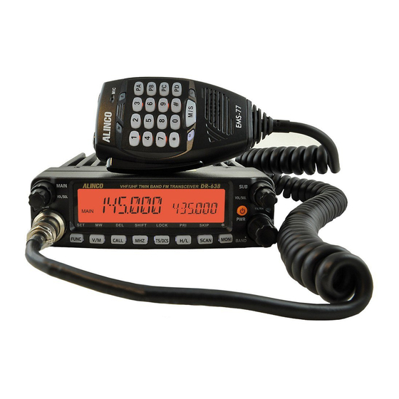
DR-638HE: VHF/UHF FM amateur transceiver
144.000-145.995MHz/430.000-439.995MHz
Use of this device is authorized in all EU and EFTA member
states(CH/ICE/LI/NOR).
Operator's license is required.
Copyright Alinco, lnc. PS0820/FNEH-NI
Printed in China
Advertisement
Table of Contents

Subscribe to Our Youtube Channel
Related Manuals for Alinco DR-638H


Summary of Contents for Alinco DR-638H
- Page 1 4-4-9 Koraibashi, Chuo-ku, Osaka 541-0043 Japan Phone: +81-6-7636-2362 Fax: +81-6-6208-3802 http://www.alinco.com E-mail:export@alinco.co.jp DR-638HE: VHF/UHF FM amateur transceiver 144.000-145.995MHz/430.000-439.995MHz Use of this device is authorized in all EU and EFTA member states(CH/ICE/LI/NOR). Operator's license is required. Copyright Alinco, lnc. PS0820/FNEH-NI Printed in China...
-
Page 2: Instruction Manual
VHF/UHF FM Mobile Transceiver DR-638H Instruction Manual Thank you for purchasing your new Alinco transceiver. Please read this manual carefully before using the product to ensure full performance, and keep this manual for future reference as it contains information on after-sales services. In case addendum or errata... -
Page 3: Before Transmitting
Introduction CE Conformity Information This device is in compliance with the essential requirements of R&TTE Thank you very much for purchasing this excellent Alinco transceiver. Directive 1999/5/EC. Our products are ranked among the finest in the world. This radio has... - Page 4 WARNING To prevent any hazard during operation of Alinco’s radio product, in this Do not use this product in close proximity to other electronics manual and on the product you may find symbols shown below. Please devices, especially medical ones. It may cause interference read and understand the meanings of these symbols before starting to to those devices.
-
Page 5: In Case Of Emergency
WARNING Handling this product: Do not plug the power-supply into the wall outlet if the contacts are dirty and/or dusty. Be sure to reduce the audio output level to minimum before Shortcircuiting and/or overheating may result in fire, electric using an earphone or a headset. Excessive audio may damage shock and/or damage to the product. -
Page 6: Environment And Condition Of Use
WARNING About power-supply CAUTION Use only reliable power supply of specific DC output range and Environment and condition of use: be mindful of the polarity of the cables and DC jack. Do not use the product in proximity to a TV or a radio. It may Always turn off the power supply when connecting or cause interference or receive interference. -
Page 7: Table Of Contents
CONTENTS New and Innovative Features ..........1 High/Mid/Low Power Setting ............13 Frequency Reverse ................13 Supplied Accessories/Optional Accessories .....2 CTCSS/DCS setting ................. 13 Supplied Accessories ............... 2 Call channel recalling ............... 13 Initial Installation ..............3 CTCSS/DCS Scan ................13 Mobile installation ................3 Dual Watch.................. - Page 8 CONTENTS Menu 52: Beep Volume control ............26 Menu 15: DTMF Encode Setup ............19 Menu 53: Talk Around ..............26 Menu 16: Squelch Mode Setup ............20 Menu 54: Microphone Speaker ............26 Menu 17: Compander ..............20 Menu 55: Memory Banks Enquiry ............ 27 Menu 19: Tone Burst Tones .............
-
Page 9: New And Innovative Features
New and Innovative Features 758 memory channels. 50 Watts of power output on the VHF band and 40 Watts on the UHF band. UU, UV, VU, VV operations. A large LCD with selectable backlit color, Keys and microphone keypads are also backlit and ensures comfortable operation in the dark. -
Page 10: Supplied Accessories/Optional Accessories
The standard accessories may vary slightly depending on the version you have purchased. Please contact your local authorized Alinco dealer should you have any questions. Alinco and authorized dealers are not responsible for any typographical errors there may be in this manual. Standard accessories may change without notice. -
Page 11: Initial Installation
Initial Installation Mobile installation Determine the appropriate angle of the transceiver, using the 3 screw The transceiver may be installed in any position in your car, where the hole positions on the side of the mounting bracket. controls and microphone are easily accessible and it does not interfere with the safe operation of the vehicle. -
Page 12: Dc Power Cable Connection
Initial Installation Reconnect any wiring removed from the negative terminal. DC Power Cable Connection Connect the DC power cable to the transceiver's power supply Mobile Operation connector. The vehicle battery must have a nominal rating of 12V. Never connect the transceiver to a 24V battery. Be sure to use a 12V vehicle battery that has sufficient current capacity. - Page 13 Initial Installation ACC terminal Connect the transceiver's DC power connector to the connector the DC power cable. Cigar-Plug connection Press the connectors firmly together until the locking tab clicks Optional EDC-43 required Before connecting the DC power to the transceiver, be sure to switch the transceiver and the DC power supply OFF.
-
Page 14: Power Supply Voltage Display
Initial Installation Power supply voltage Display Accessories Connections After connecting the transceiver to the power supply, long press the External Speaker key, enter Menu 12: Sub Band Display menu, and select DC-IN, then it If you plan to use the optional external speaker/s, There are 2 will appear current power supply voltage on the right side of Screen. -
Page 15: Front Panel Separation
Initial Installation Front Panel separation Microphone The main unit can be set with either side facing up. This can facilitate your Antenna ability to hear the speaker clearly. Position the front panel as you prefer. Slide the front panel while keeping the tab pressed. Main unit Front panel External Dual Speakers... -
Page 16: Getting Acquainted
Getting Acquainted Front panel Short press: Switches to CALL channel. Long press: When channel setting DTMF/5 [CALL] Tone, press this key can edit ANI code calling. (microphone input) Short press: Changes frequency step by 1MHz in [MHz] VFO mode. Long press: Open the frequency reverse function. Short press: Sets CTCSS and DCS values. -
Page 17: Rear Panel
Getting Acquainted Functions which can be activated while appears, after pressing the DISPLAY 8 13 14 10 15 11 1712 FUNC+V/M Programs the data into the memory. FUNC+CALL Delete settings. SHIFT FUNC+MHZ Changes shift directions. LOCK FUNC+TS/DCS Blocks the keys and dial operation FUNC+H/L Enters to the Priority monitor. -
Page 18: Microphone
Getting Acquainted Appears while open grouping function. NO. KEY FUNCTION Appears while Sub side in memory channel or Call Switches between Main and Sub bands. channel mode. Number Key Input VFO frequency or DTMF dial out etc. Appears while Channels setting in frequency reverse Switches between VFO and Memory modes. -
Page 19: Basic Operations
In VFO mode, turn the dial clockwise to increase frequency; Counterclockwise to decrease. Every Press key to turn on. Appears "ALINCO DR- click will increase or decrease frequency by one 638" then displays current frequency or channel. channel-step. To select MAIN and SUB band, Power Off press the dial. -
Page 20: Switch Between Main Band And Sub Band
Basic Operations Pressing [UP/DOWN] keys on microphone also sets channels. Transmitting is prohibited outside of the specified frequency range. "OFF" appears when PTT is pressed in the RX-only frequency and The mamory channels must be pre-programmed to operate in the memory alarming beep sounds. -
Page 21: Transmit Dtmf/2Tone/5Tone Signaling
Basic Operations Hold [PTT] key to transmit, and speak at approximately 5cm/2 inces to This function is valid only when current channel setup with offset the microphone in normal voice level. Too frequency and offset direction loud or too low voice level may cause trouble hearing at the receiving stations. -
Page 22: Dual Watch
Basic Operations CHANNEL SCAN SkIP MIC UP/DOWN key can change the scan direction. In Memory mode, turn the dial to choose the channel to skip during To enable this function, the channel shall be programmed with scanning. Press and while icon is displayed on the screen, CTCSS/DCS decode. -
Page 23: Channel Copy
Basic Operations CHANNEL COPY Bank B: CH 301 to 400 (100ch) Bank C: CH 401 to 500 (100ch) In memory mode, select the desired channel by using the dial or Bank D: CH 501 to 600 (100ch) numerical keys. Bank E: CH 601 to 700 (100ch) Press key to display and a memory channel number on the... -
Page 24: Parameter Setting Mode(Set Mode)
Parameter Setting Mode (SET MODE) Rotate the dial or use [UP/DOWN] keys to You can set the operating parameters and functions of DR-638 to best suite your demands. select ON or OFF. Press [PTT] to set and exit or press the Press and hold key until activating the function menu. -
Page 25: Menu 05: Beep Sound
Parameter Setting Mode (SET MODE) become available only within the current VFO frequency band. MENU 07: 2TONE ENCODE SELECT Press [PTT] to set and exit or press the dial to set and continue. Press and hold key until activating the function menu. Rotate the dial or use [UP/DOWN] keys to select the menu 07 2T ENC and MENU 05: BEEP SOUND press the dial. -
Page 26: Menu 09: Add Optional Signaling
Parameter Setting Mode (SET MODE) MENU 09: ADD OPTIONAL SIGNALING Press PTT to set and exit or press the dial to set and continue. Available tones Press and hold key until activating the function menu. Rotate the dial or use [UP/DOWN] keys to select CTCSS: 62.5-254.1Hz, and one self- the menu 09 TONDEC and press the dial. -
Page 27: Menu 12: Sub Band Display
Parameter Setting Mode (SET MODE) MENU 12: SUB BAND DISPLAY MENU 14: DTMF ENCODE TRANSMITTING TIME Press and hold key until activating the function menu. Rotate Press and hold key until activating the function menu. Rotate the dial or use [UP/DOWN] keys to select the dial or use [UP/DOWN] keys to select the menu 14 DTMF S and the menu 12 DSPSUB and press the dial. -
Page 28: Menu 16: Squelch Mode Setup
Parameter Setting Mode (SET MODE) MENU 16: SQUELCH MODE SETUP ON: Turn on Compander function. OFF: Turn off Compander function This parameter becomes available only when CTCSS/DCS or optional Press [PTT] to set and exit or press the DTMF/5TONE/TONE signaling has been set. dial to set and continue. -
Page 29: Menu 21: Keypad Lockout
Parameter Setting Mode (SET MODE) another transmission during a selected TOT penalty period regardless HYPER1: Super channel 1 display mode. of the [PTT] key being pressed. A beep sounds when the [PTT] key is HYPER2: Super channel 2 display mode. pressed during the TOT penalty period. -
Page 30: Menu 26: Editing Memory Name
Parameter Setting Mode (SET MODE) TX: When the Main band is transmitting, Rotate the dial or use [UP/DOWN] keys to the sub band receive is mute. select the value: RX: When the Main band is receiving, the 1-30 Minutes, total of 30 setting sub band receive is mute. -
Page 31: Menu 33: Offset Direction
Parameter Setting Mode (SET MODE) Rotate the dial or use [UP/DOWN] keys S-3: Squelch opens at 3 bar. to select the value: S-5: Squelch opens at 5 bars. TIME: Pauses 5 seconds to receive the S-9: Squelch opens at 9 bars. signal and resume scanning. -
Page 32: Menu 37: Display Mode
Parameter Setting Mode (SET MODE) Rotate the dial or use [UP/DOWN] keys to dial or use [UP/DOWN] keys to select the select the mode: menu 36 SHIFT and press the dial. RLORP: Signaling BCLO, transmitting [UP/DOWN] keys Rotate the dial or use is inhibited when a signal with to select desired value between 0 and different CTCSS/DCS setting is... -
Page 33: Menu 41: Vfo Frequency Linkage
Parameter Setting Mode (SET MODE) MENU 41: VFO FREQUENCY LINkAGE MENU 44-46: LCD BACkLIGHT Press and hold key until activating the function menu. Rotate Press and hold key until activating the the dial or use [UP/DOWN] keys to select function menu. Rotate the dial or use [UP/ the menu 41 VFOTR and press the dial. -
Page 34: Menu 49: Am Function
Parameter Setting Mode (SET MODE) This transceiver is able to record 16 calling at most. the external Dual Track speaker. Press [PTT] to set and exit or press the dial to set and continue. Press [PTT] to set and exit or press the dial to set and continue. MENU 49: AM FUNCTION MENU 52: BEEP VOLUME CONTROL Press and hold... -
Page 35: Menu 55: Memory Banks Enquiry
Parameter Setting Mode (SET MODE) Menu 60 Bank D Link ON /OFF HND SPK and press the dial. Menu 61 Bank E Link ON /OFF Rotate the dial or use [UP/DOWN] keys to Menu 62 Bank F Link ON /OFF select the value: Menu 63 Bank CH Link ON /OFF... -
Page 36: Microphone Operation
Microphone Operation means plus offset, when the LCD displays "-", means minus offset. DOWN This function is valid only when current channel set with offset frequency. NOTE Add or delete priority channel: In channel mode, press the key Numeric Keys programmed as PRI function to set priority channel, when the P1", LCD displays "... - Page 37 Microphone Operation " REV: In standby, press the key programmed CALL OUT: Calling, in standby, press the key programmed as CALL " " " function to turn-on or turn off function to transmit pre- programmed DTMF, 2TONE, Frequency Revrse function. 5TONE code.
-
Page 38: Cable Clone
Cable Clone This feature will copy the programmed data and parameters from the master unit to slave units. It copies the parameters and memory program settings. Use optional cloning cable, connect the cable between the data jacks on both master and slave. Press and hold key to power on, then hold this key until the LCD displays "CLONE". -
Page 39: Programming Software Installing And Starting
Unzip the downloaded file, unzip and click on the PL****Prolific_DriverInstaller_v*** to start installation. DR-638 utility software NOTICE: Amateur radio version software is downloadable from ALINCO.com. The manufacturer distributes the Commercial-user version to the dealers through the authorized importers/distributors only. The dealers should consult with the distributor of your area for details. -
Page 40: Maintenance
• Microphone connection is poor. Connect microphone properly. transmission does not occur. • Antenna connection is poor. Connect antenna properly. If a problem should occur, first try the troubleshooting procedure given above. If the problem persists, contact your nearest ALINCO dealer for technical assistances. -
Page 41: Specifications
Specifications General Receiver 144~146MHz Wide band Narrow band Frequency Range 430~440MHz Sensitivity ≤0.25μV ≤0.35μV (12dB SINAD) Number of Channels 758 channels Adjacent Channel ≥70dB ≥60dB 25KHz(Wide band) Selectivity Channel Spacing 20KHz(Middle band) Audio Response +1~-3dB(0.3~3KHz) +1~-3dB(0.3~2.55KHz) 12.5KHz (Narrow band) Hum & Noise ≥45dB ≥40dB 2.5KHz 、... -
Page 42: Appendix
Appendix 1024 GROUPS DCS CODE 51 GROUPS CTCSS TONE FREQUENCY(Hz) 62.5 77.0 91.5 107.2 127.3 151.4 167.9 183.5 199.5 225.7 254.1 Self 67.0 79.7 94.8 110.9 131.8 156.7 171.3 186.2 203.5 229.1 Define 69.3 82.5 97.4 114.8 136.5 159.8 173.8 189.9 206.5 233.6 71.9 85.4 100.0 118.8 141.3 162.2 177.3 192.8 210.7 241.8 74.4 88.5 103.5 123.0 146.2 165.5 179.9 196.6 218.1 250.3 The self defined CTCSS tone supports non standard codes. - Page 43 Appendix N is positive code, I is negative code, total:1024 groups. NOTE...
Need help?
Do you have a question about the DR-638H and is the answer not in the manual?
Questions and answers
Como enlasar **** repetidora
To link the Alinco DR-638H to a repeater, set the offset (shift) frequency as follows:
1. Press and hold the key until the function menu activates.
2. Rotate the dial or use [UP/DOWN] keys to select MENU 36: OFFSET FREQUENCY.
3. Press the dial to enter the menu.
4. Rotate the dial or use [UP/DOWN] keys to select the desired offset value between 0 and 100 MHz.
5. Press [PTT] to set and exit, or press the dial to confirm and continue.
This sets the frequency difference between transmit and receive, which is required for repeater operation.
This answer is automatically generated