Table of Contents
Advertisement
Quick Links
Advertisement
Table of Contents

Related Manuals for AQUAPHOR APRO WH 1000 LPH


Summary of Contents for AQUAPHOR APRO WH 1000 LPH
- Page 1 APRO WH 1000 LPH WATER PURIFICATION SYSTEM aquaphor-pro.com TP-APRO-WH-R02...
- Page 2 AQUAPHOR PRO. The translation into another language also requires a written authorization. This documentation may be exclusively entrusted to the owner of the installation or to the employees of AQUAPHOR PRO. Technical Revision No 2 modification aquaphor-pro.com...
-
Page 3: Table Of Contents
7.6.1 Example of software setup .......................... 32 Program 01: FEED PUMP (XV-01) ......................... 33 Program 02: PRETREATMENT (PTS-01) ......................... 33 Program 03: FLUSH VALVE * ..........................33 Program 04: PERMEATE VALVE NC (XV-02) ......................34 Program 05: SUPPLY PUMP (P-04) ........................34 aquaphor-pro.com TP-APRO-WH-R03... - Page 4 Setup 13: PERIODIC FLUSH DURATION ......................... 43 Setup 14: FULL TANK DELAY ..........................43 Setup 15: PERMEATE LOW FLOW ......................... 43 Setup 16: CONCENTRATE LOW FLOW ........................44 Setup 17: LOW FEED PRESSURE ..........................44 Setup 18: LOW INLET PRESSURE ........................... 44 aquaphor-pro.com TP-APRO-WH-R03...
- Page 5 9.3 Operating Mode Functionality ..........................56 9.4 Additional Information ............................57 10. MAINTENANCE ................................58 10.1 Dosing Pump Degassing ............................58 10.2 Replacing The Membrane Module ........................59 10.3 Replacing The Filter Cartridge ..........................60 10.3.1 Viking cartridge ............................60 aquaphor-pro.com TP-APRO-WH-R03...
- Page 6 Status words ................................. 75 12. RULES OF STORAGE AND TRANSPORTATION ....................78 12.1 Shipping ................................. 78 13. SERVICE AND WARRANTY ..........................79 Exclusions and Limitations ............................ 79 14. Additional Materials ..............................80 System Equipment list ............................82 Remarks ................................83 aquaphor-pro.com TP-APRO-WH-R03...
-
Page 7: General Information
CAUTION Denotes a possibly dangerous situation. Not observing this pointer can cause minor injuries. ATTENTION Denotes a possibly dangerous situation. Not observing this pointer can cause material damage. INFORMATION Denotes application pointers and other useful information. aquaphor-pro.com TP-APRO-WH-R03... -
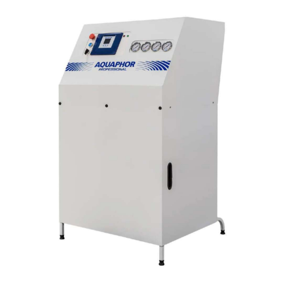
Page 8: System Overview
2. SYSTEM OVERVIEW APRO WH 1000 LPH system dimensions aquaphor-pro.com TP-APRO-WH-R03... - Page 9 TP-APRO-WH-R03...
-
Page 10: Table Of System Equipment
Check valve Permeate drainage check valve. CV-03 Check valve Check and pack pressure valve. CV-04 Check valve Concentrate check valve. CV-05 Check valve Concentrate recirculation check valve. CV-06 Check valve Stand-by permeate check flushing valve. MV-01/04 Membrane housing aquaphor-pro.com TP-APRO-WH-R03... -
Page 11: Table Of Optional Equipment
Pretreatment backwashing stage indicator Backward Switch LLS-01 Low Level Sensor Protects P-03 from dry running LLS-03 Low Level Sensor Protects P-04 from dry running HFS- High Level float Mechanically blocks water supply when the tank is overfilled 01/02 switch aquaphor-pro.com TP-APRO-WH-R03... -
Page 12: Electric Circuits
The unit is equipped with fully automated control. It can supply purified water using the logic con- troller, water level, and pressure sensors, based on an adjustable algorithm, standardized for the reverse osmosis systems manufactured by Aquaphor. ▪... -
Page 13: Electric Circuit Schemes
3.2 ELECTRIC CIRCUIT SCHEMES aquaphor-pro.com TP-APRO-WH-R03... - Page 14 TP-APRO-WH-R03...
- Page 15 TP-APRO-WH-R03...
- Page 16 TP-APRO-WH-R03...
- Page 17 TP-APRO-WH-R03...
- Page 18 TP-APRO-WH-R03...
- Page 19 TP-APRO-WH-R03...
- Page 20 TP-APRO-WH-R03...
-
Page 21: Control Panel
Resetting the current program (return to the start window SYSTEM OFF). «RO system» mode OFF - Standby mode switcher AUTO - Automatic mode CIP - Service Mode «Alarm» lamp indicator Emergency situation «Run» lamp indicator The unit operates normally aquaphor-pro.com TP-APRO-WH-R03... -
Page 22: Technical Data Description
Free chlorine mg/l Iron mg/l <0.1 Manganese mg/l <0.1 Sewage according to local regulations 5.1.2 INSTALLATION ROOMS Designation Unit Value Temperature °C 5 to 40 Lighting at least 150 Source of fresh air aerate and deaerate sufficiently aquaphor-pro.com TP-APRO-WH-R03... -
Page 23: Reverse Osmosis Data
½’’ Permeate Pressure fluctuations max. ± 1 RO salt retention rate max. 90 - 95 Operating temperature °C 30 - 40 Surrounding temperature °C 4 - 40 Electric connection EU plug Connection 1/N/PE Voltage Frequency Power Nominal current aquaphor-pro.com TP-APRO-WH-R03... -
Page 24: Installation
CAUTION : Possible contamination of the washing water / air; Infections and diarrhea ▪ Wear personal protective equipment (waterproof clothing, boots, gloves and breathing protection (e.g. particle filtering half-mask). ▪ Avoid any contact with washing water and spray mist. ▪ Provide sufficient aeration. aquaphor-pro.com TP-APRO-WH-R03... -
Page 25: General Pointers
Piping for the feed water should be either copper or plastic as iron or carbon steel pipe could increase the iron content of the feed water. Temperature of the feed water should not exceed 35° C. This unit comes equipped with pressure aquaphor-pro.com TP-APRO-WH-R03... - Page 26 Should the membranes need to be installed or replaced, be sure to notice how they were removed. The flow of water will always be from the end of the membrane with the brine seal to the end without the brine seal. aquaphor-pro.com TP-APRO-WH-R03...
-
Page 27: Configuration
7. CONFIGURATION APRO WH 1000 LPH system can be configured in two ways: ▪ By using the three-button keyboard of the controller. ▪ By using the APRO Monitor application on the screen of a mobile device. 7.1 STARTING 7.1.1 CONNECTION CAUTION: It is recommended to use eyes and hands protection while unpacking the system. -
Page 28: Configuration Via Controller Keyboard
Pressing the "OK" ▀ and "Down"▼ buttons on the three-position switch simultaneously will start the subroutine for configuring system devices. If the starting parameters meet the system's requirements, then an indication of the system operation will be dis- played on the controller screen: aquaphor-pro.com TP-APRO-WH-R03... -
Page 29: System Start-Up
7.3 SYSTEM START-UP 2. Feed Press ON 3. Feed Valve XV-01 1. Feed Pump ON LPS1 check opening 4. Valve XV-02 ON 5. Flush 5 seconds 6. RO pump P01 ON 8. Pump Press 9. High frequency XV-04 7. RO pump P02 ON HPS check check... -
Page 30: System Shut-Down
7.4 SYSTEM SHUT-DOWN 1. RO pumps OFF 2. Feed pump OFF 3. Feed Valve closing 4. Valve 05 opening 5. Flush 3 seconds 6. System shut-down 28 sec 7. Feed OK... -
Page 31: System Run
7.5 SYSTEM RUN System run panel has a few types of display, representing the current parameters of the system. Pressing “Up” and "Down"▼ buttons will switch the display to another one. Сделать значок рука – палец нажимает (поверх кар- тинки) General display •... -
Page 32: Equipment Setup
7.6 EQUIPMENT SETUP 1. Move the switch to the OFF position to start setting up the system. Perform dosing pump degassing (Maintenance, 10.1). 3. Make sure there is no leakage. 4. Check all the setups and programs (7.3, 7.4). Whenever the low level sensor is off, it is recommended to perform P-04 deaeration (Maintenance, 10.1). 7.6.1 EXAMPLE OF SOFTWARE SETUP To enter the settings menu, use the controller's three-button keyboard located under the monitor screen. -
Page 33: Program 01: Feed Pump (Xv-01)
If the program is on (✓), the valve is normally closed and operating in a described way. If the program is off, the valve closes when the maxi- mum allowed value of LLS is exceed. PROGRAM 01: FEED PUMP (XV -01) If the input water does not meet the requirements of this manual for the minimum pressure and required volume, the system can be connected to the existing water supply through the raw water supply system. -
Page 34: Program 04: Permeate Valve Nc (Xv-02)
PROGRAM 04: PERMEATE VALVE NC (XV-02) Presence of a primary permeate drainage valve (XV-02). The valve turns on when the set value of the product electrical conductivity is exceeded. During the system operation, the drainage valve opening symbol will be displayed on the controller during the frequency reset (the green arrow indicator should be in the right upper corner). -
Page 35: Program 07: Feed Flow Transmitter (Ft-02)
PROGRAM 07: FEED FLOW TRANSMITTER (FT-02) Enables/disables feed flow sensor (FT-02). PROGRAM 08: HIGH PRESSURE SWITCH (HPS-01) Enables/disables high pressure switch (HPS-01). PROGRAM 09: PERMEATE FLUSH (XV -05) Whenever the system is in stand-by mode, enables membrane flush with permeate. Permeate is supplied by XV-05 valve. -
Page 36: Program 11: Dosing Level Sw. (Lls-02)
PROGRAM 11: DOSING LEVEL SW. (LLS-02) Enables/disables low antiscalant level switch. PROGRAM 12: HIGH FREQUENCY RO Enables the frequency concentrate drainage. PROGRAM 13: HF VALVE NO Enables/Disables high frequency valve to be normally opened. Current system is lacking high frequency valve Program is not required. -
Page 37: Program 15: Permeate Conductivity (Ect-01)
PROGRAM 15: PERMEATE CONDUCTIVITY (ECT-01) Enables RO permeate conductivity sensor (ECT-01). PROGRAM 16: RAW WATER CONDUCTIVITY (ECT-02) Enables raw water conductivity sensor (ECT-02). PROGRAM 17: FEED LOW PRESSURE SENSOR (L PT-01) Enables feed low pressure sensor (LPT-01). If program is disabled, the system is protected by LPS-01. -
Page 38: Program 18: Feed Pres. Sensor 4-20 Ma (Lpt-01) *Optional
PROGRAM 18: FEED PRES. SENSOR 4-20 A (LPT-01) *OPTIONAL If the program enabled, the feed pressure sensor range is 4 – 20 mA. If the program disabled, there is an analogue sensor and its range is 0 – 5 mV. The pressure range of the sensor is 0 –... -
Page 39: Program 22: Ro High Pressure Sensor Range 0-40 *Optional
PROGRAM 22: RO HIGH PRESSURE SENSOR RANGE 0 -40 *OPTIONAL If the program enabled, the RO high pressure sensor range is 0 – 40 bar. If the program disabled, RO high pressure sensor range is 0 – 10 bar. PROGRAM 23: RO PRESSURE SENSOR 4 -20MA (HPT-01) *OPTIONAL If the program enabled, the inlet pressure sensor range is 4 –... -
Page 40: Setups
7.7 SETUPS SETUP 01: START-UP FLUSH Setting the start-up flush time. SETUP 02: SHUT-DOWN FLUSH Setting the shut-down flush time. SETUP 03: STAND-BY FLUSH Setting the stand-by flush period (period in hours). SETUP 04: HIGH CONDUCTIVITY PERMEATE WATER ALARM Setting the point for the product conductivity limit (max value). -
Page 41: Setup 05: High Conductivity Feed Water Alarm
SETUP 05: HIGH CONDUCTIVITY FEED WATER ALARM Setting the maximum value for the feed conductivity limit. SETUP 06: LOW PRESS. DELAY Setting the delay to stop the system after a signal of low input pressure is received. SETUP 07: DOSING PULSE/MIN Setting the number of pulses per minute. -
Page 42: Setup 09: Feed Flow 'K
SETUP 09: FEED FLOW ‘K’ Setting the number of pulses per liter. Note: the parameters are set by flowmeter manufacturer. RECOVERY SETUPS (SETUP-10-13) The table below represents the values required for the specific recovery percentage. The setups should be performed under 20 °C and conductivity <2000 uSM. -
Page 43: Setup 12: Periodic Flush/H
SETUP 12: PERIODIC FLUSH/H Setting the number of periodic flushes per hour. SETUP 13: PERIODIC FLUSH DURATION Setting the periodic flushing duration. SETUP 14: FULL TANK DELAY Setting the delay to stop the system after the full tank signal is received (HPS-02). SETUP 15: PERMEATE LOW FLOW Setting the minimum permeate flow signaling to stop the system (Check 8.7 Alarm- 09). -
Page 44: Setup 16: Concentrate Low Flow
SETUP 16: CONCENTRATE LOW FLOW Setting the minimum concentrate flow. SETUP 17: LOW FEED PRESSURE Setting the minimum feed water pressure. SETUP 18: LOW INLET PRESSURE Setting the minimum inlet pressure. SETUP 19: HIGH RO PUMP PRESSURE ALARM Setting the highest acceptable RO pump pressure value. -
Page 45: Setup 20: System Stop Permeate Tank Pressure Alarm
SETUP 20: SYSTEM STOP PERMEATE TANK PRESSURE ALARM Setting the highest acceptable permeate tank pressure value. SETUP 21: SYSTEM START PERMEATE TANK PRESSURE Setting the starting value of permeate tank pressure. SETUP 22: CARTRIDGE FILTER PRESSURE DROP ALARM Setting the minimum value of the cartridge filter pressure. SETUP 23: CARTRIDGE FILTER RESOURCE Setting the volume of cartridge filter resource. -
Page 46: Setup 24: System Id Number
SETUP 24: SYSTEM ID NUMBER Setting the system ID number (1-255). SETUP 25: YEAR Setting the year (18-50). SETUP 26: DATE/MONTH Setting the date (DD:MM). SETUP 27: TIME Setting the time (hh:mm). -
Page 47: Alarms And Troubleshooting
8. ALARMS AND TROUBLESHOOTING If there is any critical error in operation, the system is switched to the "Alarm" error mode. The "Alarm" window contains information about: ▪ the name(s) of critical error(s) ▪ the number of critical errors ▪ the time until the next attempt to restore the system To enter the standby state and return to the start window, move the switch to the OFF position. -
Page 48: Alarm-03: Antiscalant Tank Low Level * Not Required
8.3 ALARM-03: ANTISCALANT TANK LOW LEVEL * NOT REQUIRED The error occurs when there is no signal from the LLS-02 low level sensor in the antiscalant T-02 tank for 10 seconds. Solution: The error is solved when the signal from the low water level sen- sor is received. -
Page 49: Alarm-06: High Inlet Pressure To Ro Membrane Unit
8.6 ALARM-06: HIGH INLET PRESSURE TO RO MEMBRANE UNIT The error occurs when the osmosis pump is in process, and there is no signal from the HPS-02 high-pressure sensor at the membrane inlet for 10 seconds. After a problem occurs, the system will try to restart it again. If the problem persists, the osmosis system will stop until the problem is resolved. -
Page 50: Alarm-09: Minimum Permeate Flow
8.9 ALARM-09: MINIMUM PERMEATE FLOW The error occurs when the pump of the RO system (P-01) is running, and the osmosis system permeate flow value is less than the set value (Setup-14) for 5 minutes. After a problem occurs, the system will try to restart again. If the problem persists, the osmosis system will stop until the problem is resolved. -
Page 51: Alarm-12: High Feed Conductivity
8.12 ALARM-12: HIGH FEED CONDUCTIVITY The error occurs when the pump of the RO system P-03 is working, and the high feed conductivity of the raw water of the RO system is greater than the set value for 5 minutes. After a problem occurs, the system will try to restart it again. -
Page 52: Alarm-17: Permeate Pressure Sensor
8.17 ALARM-17: PERMEATE PRESSURE SENSOR The error occurs when the permeate pressure value is higher than the set value (Setup-20) for 5 minutes. Solution: Check the sensor and cable connection. If there is an error after checking, then replace the sensor. 8.18 WARNINGS Solution: Replace the cartridge and press RESET for 5 sec. - Page 53 Alarm № Symptoms Possible causes Corrective Action Low level in Low level in the raw water tank T- Check the presence of raw water; other- Alarm-01 the raw water wise, check RO water supply and LLS- tank 01 functionality. Alarm-02 Pretreatment The pre-filtration system is in the Check the functionality of pretreatment...
-
Page 54: Equipment Testing
8.19 EQUIPMENT TESTING Equipment testing mode allows to check the condition of each system’s element. Turn the switch to the CIP position. Press ▼ for 3 seconds. The following screen will appear: Press ▀ to enable/disable the system’s element and switch to the next one. To close equipment testing mode, put the switch to the OFF position. -
Page 55: Android App (Apro App)
Alarms display 9.1 SETTING UP 1. Download and install the APRO Monitor app from the official website of the system manufacturer (aquaphor-pro.com) to your mobile device. The link can be found in the footer: Open the app. Configure the connection. -
Page 56: System Configuration
9.2 SYSTEM CONFIGURATION ! It is possible to make changes to the system configuration and parame- ters only in OFF mode. The starting screen displays the system configuration and available reverse osmosis (RO) system’s option (1). Sys- tem Settings window (2) has two subparts: “Configuration” enables or disables programs 01-16 (page ... make refer- ence to the programs part). -
Page 57: Additional Information
The “Log“ button of the context menu shows statistics and log of the system. It is possible to share the statistics with other users and devices. The “Share” button of the context menu suggests several options (browser and messenger). 9.4 ADDITIONAL INFORMATION The context menu also contains the “Help”... -
Page 58: Maintenance
10. MAINTENANCE 10.1 DOSING PUMP DEGASSING After antiscalant replacement, it is required to perform dosing pump degassing. Dosing head, exploded view. 1. Safety diaphragm 2. Flange 3. O-ring 4. Diaphragm 5. Valve on discharge side 6. Valve on suction side 7. -
Page 59: Replacing The Membrane Module
10.2 REPLACING THE MEMBRANE MODULE ATTENTION: Blocking of the module. Ensure the right installation direction (arrow on the module) while installing the module. INFORMATION The unit should be commissioned again after a module replacement. -
Page 60: Replacing The Filter Cartridge
10.3 REPLACING THE FILTER CARTRIDGE 10.3.1 VIKING CARTRIDGE 1. Turn OFF water supply and relieve pressure; 2. Unscrew the coupling nuts (4) and disconnect the quick junction (3); 3. having turned OFF the handle (6), take off the locking plate (5) from the holder (1);... -
Page 61: Yearly Check And Maintenance
10.4 YEARLY CHECK AND MAINTENANCE 10.4.1 CABLES AND CABLE CONNECTION WARNING: uncontrolled motion of the unit; danger of injury Turn OFF the main switch and prevent the reactivation. DANGER : Electric shock, Danger of life ▪ Turn OFF the main switch and avoid its reactivation. ▪... -
Page 62: Automatic Concentrate Valve Flush Opening
10.4.2 AUTOMATIC CONCENTRATE VALVE FLUSH OPENING DANGER : Electric shock, Danger of life ▪ Turn OFF the main switch and avoid its reactivation. ▪ Let only the competent staff carry out the electric work. ▪ Ensure the absence of power before starting to work. ▪... -
Page 63: Membrane Functioning Tips
10.5 MEMBRANE FUNCTIONING TIPS 10.5.1 LOW FLOW If the system suffers from loss of normalized permeate flow performance and the problem can be localized, the gen- eral rule is: ▪ First stage problem: deposition of particulate matter; initial biofouling ▪ Last stage problem: scaling ▪... -
Page 64: Low Flow And Low Solute Passage
3. Scaling Scaling is a water chemistry problem originating from the precipitation and deposition of sparingly soluble salts. The typical scenario is a brackish water system operated at high recovery without proper pretreatment. Scaling usually starts in the last stage and then moves gradually to the upstream stages. Waters containing high concen- trations of calcium, bicarbonate and/or sulfate can scale a membrane system within hours. -
Page 65: High Solute Passage
10.5.4 HIGH SOLUTE PASSAGE High solute passage at normal permeate flow may have different causes. 1. Leaking O-Ring Leaking O-rings can be detected by the probing technique. O-rings may leak after exposure to certain chemicals or mechanical stress, e.g., element movement caused by water hammer. -
Page 66: Membrane Cleaning (Cip)
10.6 MEMBRANE CLEANING (CIP) Membranes can become contaminated after being used over time. There are such pollutants as colloids, biofilms, and biological matter. These contaminants can be absorbed by membrane, and the membrane system's pipes, conse- quentially, the system's performance will decrease. ▪... - Page 67 Empty the container, disconnect all pipes from the CIP kit, screw the CIP plugs back, return the system to its initial state, and proceed to the stage of flushing the system. Move the switch at the top to the CIP position to enter the CIP mode. a) Press “Ok”...
-
Page 68: Callibration
10.7 CALLIBRATION The conductivity requires periodic calibration. Calibration is usually required after cleaning the sensor. APRO con- troller requires multipoint calibration: calibration solutions of 1413 mkS, 84 mkS, and air for 0 mkS calibration. a. Switch the system to OFF position. b. - Page 69 f. The screen switches to permeate conductivity ‘84 mkS’ calibration screen. Place the sensor in the calibration solution 84 mkS. Make sure the sensor do not touch the bottom of the jar. Press OK ⬛ button. Hold the sensor into the solution while the screen shows WAIT mode.
- Page 70 touch the bottom of the jar. Press OK ⬛ button. Hold the sensor into the solution while the screen shows WAIT mode. k. After finishing the calibration, the calibration menu will appear: Place permeate sensor in 84 mkS solution and feed sensor in 1413 mkS solution. If the values are the same (or close) to the standard ones, press SAVE ⬛...
-
Page 71: Us/Cm To Ppm Convertion Table
S/CM TO PPM CONVERTION TABLE µS/cm µS/cm µS/cm 1000 1575 1575 1300 2500 1700 3000 1575 3400 2400 4000 2750 11.0 4500 3150 13.5 5000 3500 16.0 5500 3900 19.0 6000 4300 22.0 6500 4700 24.5 7000 5000 27.5 7500 5400 33.0 8000... -
Page 72: Preservation Of Ro And Nf Systems
10.8 PRESERVATION OF RO AND NF SYSTEMS The elements of RO system must be preserved any time the plant is shut down for more than a maximum of 48 h to prevent biological growth. Depending on the previous operational history of the plant, it will be necessary in almost all cases to clean the membranes prior to shut-down and preservation. -
Page 73: System Information Collection Via Modbus
11. SYSTEM INFORMATION COLLECTION VIA MODBUS 11.1 MODBUS COMMUNICATION PORT SETPOINTS Modbus communication port are integrated in control panel. This provides communication from the control panel to a field Modbus bus network. When powered, the water system will be able to communicate via the secondary terminals labeled XT20-1A, XT20-1B, and XT20-G as a slave device. -
Page 74: Control Word
Parameter Address Unit Type Start up permit* (Status word #4) 0025 16-bit unsigned int Output Values* (Status word #3) 0026 32-bit unsigned int Errors* (Status word #5) 0028 32-bit unsigned int Detected Errors* (Status word #5) 0030 32-bit unsigned int Startup Errors* (Status word #6) 0032 32-bit unsigned int... -
Page 75: Modbus Registers
11.5 MODBUS REGISTERS STATUS WORDS “Config State” – address 0001-0002, 32 bit unsigned. “Read only”. 0001 0002 Name Name Permeate Conductivity Tr Feed Pump Config Raw Water Conductivity Tr Pretreatment Config Flush Valve Config Cond/TDS uSm/PPM Imperial Units Reserved Feed low pressure sensor Permeate Valve NC Feed pressure sensor 4-20mA Supply Pump... - Page 76 “Output Values” – address 0026-0027, 32 bit unsigned. “Read only” 0026 0027 Name Name Feed Valve LPS2 Permeate Drain HPS1 Flush Valve LLSwT1 HF Valve LLSwT2 Permeate Flush LLSwT3 Valve Close HLSwT3 Valve Power Pretreatment Feed Pump RO Pump Recirc Pump Permeate Pump Antisc.
- Page 77 Name Name Permeate Pressure Sensor Error Feed Tank Low Level Pretreatment Signal problem Dosing Tank Low Level Feed Pressure Low Inlet Pressure Low RO Pressure High RO Pump Overload Permeate Conductivity High Permeate Low Flow Concentrate Low Flow RO Tank Low Level Feed Conductivity High Cartridge Resource Ended Feed Pressure Sensor Error...
-
Page 78: Rules Of Storage And Transportation
12. RULES OF STORAGE AND TRANSPORTATION The RO system should be stored in plastic packaging, in a closed carton, in closed spaces with natural ventilation, with a relative humidity no higher than 80%, at a temperature not lower than +3 °C and not higher than 50 °C. Transportation and storage of the RO system are always in a vertical position. -
Page 79: Service And Warranty
• Damage or loss resulting from removal, improper repair, modification of the product, or improper maintenance including damage caused by chlorine or chlorine related products. • Damage or loss resulting from acts which are not the fault of Aquaphor or which the Product is not specified to tolerate. -
Page 80: Additional Materials
14. ADDITIONAL MATERIALS... -
Page 82: System Equipment List
SYSTEM EQUIPMENT LIST Name Material onnection Code Size 1’’ F-01 Cartridge Filter Housing W0007320 1’’ P-01 Pressure pump W0005977 ½’’ DP-01 Dosing pump PDDE610B 1’’ P-05 Recirculation pump W0007888 ¼’’ LPS-01 Low pressure switch BRASS W0002424 ¼’’ LPS-02 Low pressure switch BRASS W0002424 LLS-01... -
Page 83: Remarks
REMARKS...
Need help?
Do you have a question about the APRO WH 1000 LPH and is the answer not in the manual?
Questions and answers