Advertisement
Quick Links
Advertisement

Related Manuals for Grizzly H6087


Summary of Contents for Grizzly H6087
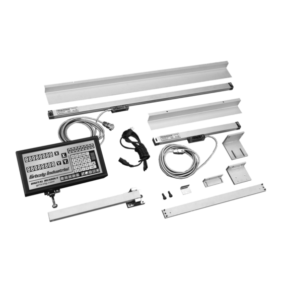
- Page 1 Digital Readout System MODEL H6087-H6098 INSTALLATION MANUAL COPYRIGHT © JUNE, 2004 BY GRIZZLY INDUSTRIAL, INC. WARNING: NO PORTION OF THIS MANUAL MAY BE REPRODUCED IN ANY SHAPE OR FORM WITHOUT THE WRITTEN APPROVAL OF GRIZZLY INDUSTRIAL, INC. #CA6351 PRINTED IN CHINA...
-
Page 2: Installation Instructions
Figures 2 & 3, it is important to ensure that the dial indicator is perpendicular to the measured surface to also avoid the cosine measurement error. Figure 2. Horizontal scale alignment. Figure 3. Vertical scale alignment. Digital Readout System... -
Page 3: Location Selection
The mounting strip, shown in Figure 5, must be as short as possible to provide a rigid surface. Figure 5. Mounting strip. Digital Readout System A clearance of at least " between the scale and scale cover is necessary (Figure 6). -
Page 4: Installation Requirements
0.1 mm of each other.. —Perpendicular mounting Figure 11: The two mounting surfaces must be less than 0.1 mm out of square. 0" ± .008" Figure 9. Parallel mounting. " .709 ± .008 Figure 10. More parallel mounting. Digital Readout System .004" .002"... - Page 5 .04", as shown in Figure 12. —For scale travel longer than 37.4" mm (Figure 13), the maximum alignment paral- lelism error must be less than 0.06". Digital Readout System > .04" Figure 12. Alignment, less than 37.4" travel. >...
- Page 6 Generally the scale reads in the correct direction with the label of the scale exposed. Lathe Scale Installation: Before fitting the scale, connect the "X" axis to the cross slide to allow the diameter function to work. Digital Readout System...
-
Page 7: Scale Setup
Figure 16. Mounting scale on backing plate. Digital Readout System When the scale is mounted, fix the reader head to the saddle. If necessary, shim the head to ensure that it is parallel and in-line with the scales (Figure 17). - Page 8 (Figure 21), and around the scale to allow for the cover to protect the scale (Figure 22), where exces- sive coolant and metal shavings are present. Figure 21. Bracket mounting location. Figure 22. Mounted scale cover. Digital Readout System...
- Page 9 (Figure 25) with the open side of the scale facing down, and must be parallel to the bed. Digital Readout System Figure 25. Longitudal scale mounting on lathe. Mount the reader head to the saddle with the provided brackets (Figure 26).
- Page 10 -10- Digital Readout System...
- Page 12 Buy Direct and Save with Grizzly Visit Our Website Today And Discover Why • SECURE ORDERING • ORDERS SHIPPED WITHIN 24 HOURS • E-MAIL RESPONSE WITHIN ONE HOUR – Trusted, Proven and a Great Value! ® Grizzly Is The Industry Leader! ®...
Need help?
Do you have a question about the H6087 and is the answer not in the manual?
Questions and answers