Table of Contents
Advertisement
Quick Links
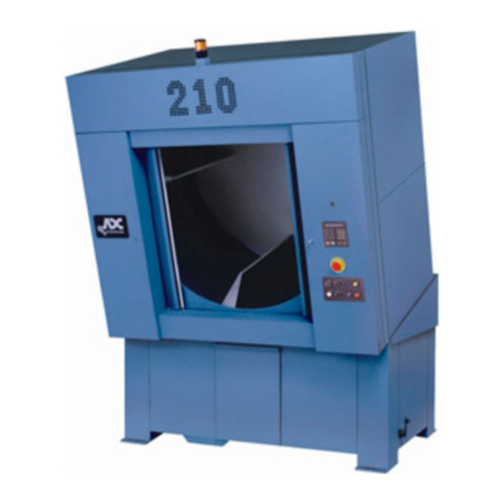
AD-210 / ML-210
Installation Manual
Phase 7 / Non-Coin / 650,000 Btu/hr
with Non-Tilting Options
! ! ! ! !
WARNING:
FIRE OR EXPLOSION HAZARD
Failure to follow safety warnings exactly
could result in serious injury, death or
property damage.
– Do not store or use gasoline or other
flammable vapors and liquids in the
vicinity of this or any other appliance.
– WHAT TO DO IF YOU SMELL GAS
● ● ● ● ●
Do not try to light any appliances.
● ● ● ● ●
Do not touch any electrical switch;
do not use any phone in your
building.
● ● ● ● ●
Clear the room, building or area of
all occupants.
● ● ● ● ●
Immediately call your gas supplier
from a neighbor's phone. Follow
the gas supplier's instructions.
● ● ● ● ●
If you cannot reach your gas
supplier, call the fire department.
– Installation and service must be
performed by a qualified installer, service
agency or the gas supplier.
! ! ! ! !
AVERTISSEMENT:
RISQUE D'INCENDIE OU D'EXPLOSION
Le non-respect des avertissements de
sécurité pourrait entraîner des blessures
graves, la mort ou des dommages
matériels.
– N'entreposer pas et n'utilisez pas
d'essence ni d'autres vapeurs ou
liquides inflammables dans le voisinage
de cet appareil ou de tout autre appareil.
– QUE FAIRE SI VOUS SENTEZ UNE
ODEUR DE GAZ
● ● ● ● ●
Ne tentez pas d'allumer d'appareil.
● ● ● ● ●
Ne touchez à aucun interrupteur. Ne
vous servez pas des téléphones se
trouvant dans le bâtiment où vous
vous trouvez.
● ● ● ● ●
Évacuez la pièce, le bâtiment ou la zone.
● ● ● ● ●
Appelez immédiatement votre
fournisseur de gaz depuis un voisin.
Suivez les instructions du fournisseur.
● ● ● ● ●
Si vous ne pouvez rejoindre le
fournisseur de gaz, appelez le service
des incendies.
– L'installation et l'entretien doivent être
assurés par un installateur ou un service
d'entretien qualifié ou par le fournisseur
de gaz.
American Dryer Corporation
88 Currant Road, Fall River MA 02720-4781 USA
Telephone: +1 (269) 923-3000 / Fax: +1 (508) 678-9447
e-mail: mdl-service@whirlpool.com / www.adclaundry.com
ADC Part No. 113549 -8
Advertisement
Table of Contents

Related Manuals for American Dryer Corp. AD-210


Summary of Contents for American Dryer Corp. AD-210
- Page 1 AD-210 / ML-210 Installation Manual Phase 7 / Non-Coin / 650,000 Btu/hr with Non-Tilting Options ! ! ! ! ! ! ! ! ! ! WARNING: AVERTISSEMENT: FIRE OR EXPLOSION HAZARD RISQUE D’INCENDIE OU D’EXPLOSION Failure to follow safety warnings exactly Le non-respect des avertissements de sécurité...
- Page 2 Retain This Manual in a Safe Place for Future Reference This product embodies advanced concepts in engineering, design, and safety. If this product is properly maintained, it will provide many years of safe, efficient, and trouble free operation. Only qualified technicians should service this equipment. OBSERVE ALL SAFETY PRECAUTIONS displayed on the equipment or specified in the installation manual included with the dryer.
- Page 3 In the State of Massachusetts, the following installation instructions apply: ■ Installations and repairs must be performed by a qualified or licensed contractor, plumber, or gas fitter qualified or licensed by the State of Massachusetts. ■ Acceptable Shut-off Devices: Gas Cocks and Ball Valves installed for use shall be listed.
- Page 4 WARNING UNDER NO CIRCUMSTANCES should the dryer door switches, lint drawer switch, heat safety circuit ever be disabled. DO NOT MODIFY THIS APPLIANCE. The dryer must never be operated with any of the back guards, outer tops, or service panels removed. PERSONAL INJURY OR FIRE COULD RESULT. DRYER MUST NEVER BE OPERATED WITHOUT THE LINT FILTER/SCREEN IN PLACE, EVEN IF AN EXTERNAL LINT COLLECTION SYSTEM IS USED.
-
Page 5: Table Of Contents
Table of Contents SECTION I IMPORTANT INFORMATION ................3 A. Receiving and Handling ........................3 B. Safety Precautions .......................... 4 SECTION II SPECIFICATIONS/DIMENSIONS AND COMPONENT LOCATION....7 A. Specifications (Gas and Steam) ...................... 7 B. Dimensions and Component Location .................... 8 SECTION III INSTALLATION PROCEDURES ................ - Page 6 SECTION VI ROUTINE MAINTENANCE ................. 45 A. Cleaning ............................45 B. Adjustments ..........................47 C. Lubrication ............................. 47 SECTION VII COMPONENT SYSTEM DESCRIPTIONS ............48 A. Tumbler Drive System ........................48 B. Tumbler ............................49 C. Air Blower Drive System ....................... 49 D.
-
Page 7: Section I
SECTION I IMPORTANT INFORMATION A. RECEIVING AND HANDLING The dryer is shipped in a protective stretch wrap cover with protective cardboard corners and top cover (or optional box) as a means of preventing damage in transit. Upon delivery, the dryer and/or packaging, and wooden skid should be visually inspected for shipping damage. -
Page 8: Safety Precautions
B. SAFETY PRECAUTIONS WARNING: For your safety, the information in this manual must be followed to minimize the risk of fire or explosion or to prevent property damage, personal injury, or loss of life. WARNING: The dryer must never be operated with any of the back guards, outer tops, or service panels removed. - Page 9 8. The possible presence of residual quantities of aggressive or decomposed chemicals in the load may produce damage to the machine and harmful fumes. 9. A program should be established for the inspection and cleaning of lint in the heating unit area, exhaust ductwork, and inside the dryer.
- Page 10 CE ONLY IMPORTANT: This appliance must only be installed and operated in the country of destination indicated on the dryer’s data plate. If the appliance is to be installed and operated in a country other than the one indicated on the data plate, a data plate amendment must be obtained from American Dryer Corporation.
-
Page 11: Specifications/Dimensions And Component Location
SECTION II SPECIFICATIONS / DIMENSIONS AND COMPONENT LOCATION A. SPECIFICATIONS (GAS AND STEAM) MAXIMUM CAPACITY (DRY WEIGHT) 200 lb 90.72 kg 158.75 cm TUMBLER DIAMETER 62-1/2” TUMBLER DEPTH 42” 106.7 cm 2,109.60 L TUMBLER VOLUME 74.5 cu ft TUMBLER / DRIVE MOTOR 3 hp 2.24 kW DOOR OPENING... -
Page 12: Dimensions And Component Location
B. DIMENSIONS AND COMPONENT LOCATION 210* NON-TILT GAS MODEL NOTE: ADC reserves the right to make changes in specifications at any time without notice or obligation. American Dryer Corporation 113549 - 8... - Page 13 210* NON-TILT STEAM MODEL NOTE: ADC reserves the right to make changes in specifications at any time without notice or obligation. 113549 - 8 www.adclaundry.com...
-
Page 14: Installation Procedures
SECTION III INSTALLATION PROCEDURES Installation should be performed by competent professional in accordance with local, state, and country codes. In the absence of these codes, the installation must conform to applicable American National Standards: National Fuel Gas Code ANSI Z223.1/NFPA 54 and National Electric Code ANSI/NFPA 70, or in Canada, the installation must conform to applicable Canadian Standards: Natural Gas and Propane Installation Code CSA B149.1 and Canadian Electric Code CSA C22.1. - Page 15 1. Reassembly Instructions For Gas Dryer Shipped In Two (2) Pieces 113549 - 8 www.adclaundry.com...
- Page 16 a. Reassembly Instructions For Non-Tilt Gas Dryers: Lift the tumbler section onto the base. 1) The dryer has four (4) support posts assemblies, which are located in each corner of the base. On top of each post assembly is a clevis block, which must be bolted to the tumbler section. Use the 4-1/2”...
- Page 17 2. Reassembly Instructions For Steam Dryer Shipped In Two (2) Pieces 113549 - 8 www.adclaundry.com...
- Page 18 a. Reassembly Instructions For Non-Tilt Steam Dryers: Lift the tumbler section onto the base. 1) The dryer has four (4) support posts assemblies, which are located in each corner of the base. On top of each post assembly is a clevis block, which must be bolted to the tumbler section. Use the 4-1/2”...
-
Page 19: Location Requirements
B. LOCATION REQUIREMENTS Before installing the dryer, ensure the location conforms to local codes and ordinances. In the absence of such codes or ordinances the location must conform with National Fuel Gas Code ANSI Z223.1/NFPA 54, or in Canada, the installation must conform to applicable Canadian Standards: Natural Gas and Propane Installation Code CSA B149.1. -
Page 20: Fresh Air Supply Requirements
C. FRESH AIR SUPPLY REQUIREMENTS This appliance may only be installed in a room that meets the appropriate ventilation requirements specified in the national installation regulations. When the dryer is operating, it draws in room air, heats it, passes this air through the tumbler, and exhausts it out of the building. -
Page 21: Exhaust Requirements
D. EXHAUST REQUIREMENTS NOTE: For 1 door dryers, the 20-inch (50.8 cm) diameter exhaust duct exits from the rear of the base. For 2 door dryers, the 20-inch (50.8 cm) diameter exhaust duct exits from the left side of the base. 1. - Page 22 The internal dimensions of the dryer’s rectangular exhaust vent ductwork are 8-inches x 20-inches (20.3 cm x 50.8 cm). A transition piece 20-inches (50.8 cm) in diameter round is supplied. The location’s exhaust duct must be the minimum exhaust size requirement of (20-inches [50.8 cm] round duct or 315 square inches [2,032 square centimeters] square duct) the ductwork from the dryer to the outside exhaust outlet for a horizontal run, with no more than one (1) elbow must not exceed 30 feet (9.14 meters) for gas and 20 feet (6.09 meters) for steam dryers.
- Page 23 210 STEAM DRYER 6,500 CFM (184 CMM) HORIZONTAL DRYER VENTING 113549 - 8 www.adclaundry.com...
- Page 24 210 GAS DRYER 5,300 CFM (150.08 CMM) VERTICAL DRYER VENTING 210 STEAM DRYER 6,500 CFM (184 CMM) VERTICAL DRYER VENTING American Dryer Corporation 113549 - 8...
- Page 25 210 GAS DRYER 5,300 CFM (150.08 CMM) VERTICAL / HORIZONTAL DRYER VENTING 210 STEAM DRYER 6,500 CFM (184 CMM) VERTICAL / HORIZONTAL DRYER VENTING 113549 - 8 www.adclaundry.com...
- Page 26 a. Outside Ductwork Protection 1) To protect the outside end of the horizontal ductwork from the weather, a 90° elbow bent downward should be installed where the exhaust exits the building. If the exhaust ductwork travels vertically up through the roof, it should be protected from the weather by using a 180° turn to point the opening downward.
-
Page 27: Compressed Air Supply System
E. COMPRESSED AIR SUPPLY SYSTEM A clean, dry, and regulated air supply of 80 PSI (5.51 bar) compressed air must be supplied to the dryer. The connection size is 1/8” N.P.T. No air filtering or pressure regulating devices are provided with the standard non-tilt dryer. - Page 28 b. Steam Dryers The air line supply connection is made into the 1/8” N.P.T. tee, which is located at the left hand side of the top of the dryer. (Refer to the illustration below.) American Dryer Corporation 113549 - 8...
-
Page 29: Electrical Information
F. ELECTRICAL INFORMATION 1. Electrical Requirements ALL electrical connections must be made by a properly licensed and competent electrician. This is to ensure that the electrical installation is adequate and conforms to local, state, and national regulations or codes of the country of destination. - Page 30 2. Electrical Service Specifications 210 NON-TILT (GAS – REAR EXHAUST) 7.5 hp Blower Motor / 3 hp Drive Motor ELECTRICAL SERVICE SPECIFICATIONS (PER DRYER) IMPORTANT: 208 VAC AND 230/240 VAC ARE NOT THE SAME. When ordering, specify exact voltage. NOTES: When fuses are used they must be dual element, time delay, current limiting, class RK1 or RK5 ONLY .
- Page 31 210 NON-TILT (STEAM / GAS – SIDE EXHAUST) 15 hp Blower Motor / 3 hp Drive Motor ELECTRICAL SERVICE SPECIFICATIONS (PER DRYER) IMPORTANT: 208 VAC AND 230/240 VAC ARE NOT THE SAME. When ordering, specify exact voltage. NOTES: When fuses are used they must be dual element, time delay, current limiting, class RK1 or RK5 ONLY .
- Page 32 3. Electrical Connections NOTE: A wiring diagram is included with each dryer and is located in the blueprint pocket inside the left side control cabinet. The main electrical input connections to the dryer are the 3-phase (3ø) power leads (L1, L2, and L3), GROUND, and in the case of 4 wire service, the NEUTRAL.
-
Page 33: Gas Information
G. GAS INFORMATION It is your responsibility to have all plumbing connections, materials, and workmanship conform to local and state regulations or codes of the country of destination. In the absence of such codes, all plumbing connections, materials, and workmanship must conform to the applicable local requirements. In the USA this is National Fuel Gas Code ANSI Z223.1/NFPA 54, or in Canada, Natural Gas and Propane Installation Code CSA B149.1. - Page 34 2. Technical Gas Data a. Gas Specifications For Australia, refer to data plate. TYPE OF GAS NATURAL PROPANE 8.7 mb 26.1 mb Manifold Pressure* 3.5 inches W.C. 10.5 inches W.C. 14.92 - 26.1 mb 27.4 - 32.37 mb In-Line Pressure 6.0 - 10.5 inches W.C.
- Page 35 3. Piping Connections ALL components/materials must conform to National Fuel Gas Code Specifications ANSI Z223.1-LATEST EDITION, or in Canada, CAN/CGA-B149.1-M91 (Natural Gas) or CAN/CGA-B149.2-M91 (Propane Gas) or LATEST EDITION (for General Installation and Gas Plumbing), as well as local codes and ordinances and must be done by a qualified professional.
-
Page 36: Water Supply Connection For Sensor Activated Fire Extinguishing (S.a.f.e.) System
Consistent gas pressure is essential at ALL gas connections. It is recommended that a 1-inch (2.54 cm) pipe gas loop be installed in the supply line servicing a bank of dryers. An in-line pressure regulator must be installed in the gas supply line (header) if the (natural) gas pressure exceeds 12.0 inches (29.9 mb) of water column pressure. -
Page 37: Steam Information
I. STEAM INFORMATION It is your responsibility to have ALL steam plumbing connections made by a qualified professional to assure that the installation is adequate and conforms to local and state regulations or codes. IMPORTANT: Failure to comply with the requirements stipulated in this manual can result in component failure, which will VOID THE WARRANTY. - Page 38 a. The presence of condensate in the steam supply line will cause water hammer and subsequent heat exchanger (steam coil) failure. The steam supply connection into the main supply line must be made within a minimum 10-inch (25.4 cm) riser. This will prevent any condensate from draining towards the dryer. b.
- Page 39 4. Steam Damper Air System Connections The dryer is manufactured with a pneumatic (piston) damper system, which requires an external supply of compressed air. The air connection is made at the left hand side on top of the dryer. a. Air Requirements Compressed Air Supply Air Pressure Normal...
- Page 40 5. Steam Damper System Operation The steam damper, as shown in the illustration below, allows the coil to stay constantly charged eliminating repeated expansion and contraction. When the damper is opened, the air immediately passes through the already hot coil, providing instant heat to start the drying process. When the damper is closed, ambient air is drawn directly into the tumbler, allowing a rapid cool down.
- Page 41 6. Steam Damper Air Piston (Flow Control) Operation Adjustment Steam damper operation was tested and adjusted prior to shipping at 80 PSI (5.51 bar). If steam damper adjustment is necessary, locate the flow control valve and make the necessary adjustments as noted below. 113549 - 8 www.adclaundry.com...
-
Page 42: Preoperational Test
J. PREOPERATIONAL TEST ALL dryers are thoroughly tested and inspected before leaving the factory. However, a preoperational test should be performed before the dryer is publicly used. It is possible that adjustments have changed in transit or due to marginal location (installation) conditions. - Page 43 NOTE: Dryer can be stopped at any time by opening the main door or by pressing the “CLEAR/STOP” key. To restart the dryer, press the “ENTER/START” key or a preprogrammed cycle key (i.e., “E”). NOTE: Pressing keypad key “A,” “B,” “C,” “D,” or “F” will also start the dryer. The six preprogrammed drying cycles (“A”...
-
Page 44: Preparation For Operation/Start-Up
2) Make a complete operational check of ALL safety related circuits (i.e., lint drawer switch and sail switch on gas models). 3) Reversing tumbler dryers should never be operated with less than a 132 lb (59.9 kg) load (dry weight), since the load’s weight affects tumbler coast time during a direction reversal command. -
Page 45: Shutdown Instructions
NOTE: LINT DRAWER MUST BE ALL THE WAY IN PLACE TO ACTIVATE SAFETY SWITCH OTHERWISE THE DRYER WILL NOT START. 9. Rotate the tumbler by hand to be sure it moves freely. L. SHUTDOWN INSTRUCTIONS If the dryer is to be shutdown (taken out of service) for a period of time, the following must be performed: 1. -
Page 46: Service / Parts Information
SECTION IV SERVICE / PARTS INFORMATION A. SERVICE 1. Service must be performed by a qualified trained technician, service agency, or gas supplier. If service is required, contact the reseller from whom the ADC equipment was purchased. If the reseller cannot be contacted or is unknown, contact the ADC Service Department for a reseller in your area. -
Page 47: Warranty Information
SECTION V WARRANTY INFORMATION A. RETURNING WARRANTY CARDS 1. Before any dryer leaves the ADC factory test area, a warranty card is placed on the back side of the main door glass. These warranty cards are intended to serve the customer where we record the individual installation date and warranty information to better serve you should you file a warranty claim. - Page 48 2. Each part must be tagged with the following information: a. Model number and serial number of the dryer from which part was removed. b. Nature of failure (be specific). c. Date of dryer installation. d. Date of part failure. e.
-
Page 49: Routine Maintenance
SECTION VI ROUTINE MAINTENANCE A. CLEANING A program and/or schedule should be established for periodic inspection, cleaning, and removal of lint from various areas of the dryer, as well as throughout the ductwork system. The frequency of cleaning can best be determined from experience at each location. - Page 50 EVERY 3 MONTHS Retighten setscrews in the collars of the four (4) 1-1/2” diameter tumbler drive shaft bearings. Clean lint accumulation from the gas valve/burner area at the top of the dryer, the fan (impellor) motor, and the fan/ impellor bearings located in the dryer’s base. NOTE: To prevent damage, avoid cleaning and/or touching ignitor/flame-probe assembly.
-
Page 51: Adjustments
B. ADJUSTMENTS 7 DAYS AFTER INSTALLATION AND EVERY 6 MONTHS THEREAFTER Inspect bolts, nuts, screws, (bearing setscrews), grounding connections, and nonpermanent gas connections (unions, shutoff valves, and orifices Motor and drive belts should be examined. Cracked or seriously frayed belts should be replaced. -
Page 52: Component System Descriptions
SECTION VII COMPONENT SYSTEM DESCRIPTIONS A. TUMBLER DRIVE SYSTEM The tumbler is supported and driven by four (4) 11-inch diameter drive wheels. Two (2) of these wheels are attached to a 1-1/2” diameter idler shaft, while the other two (2) are attached to a 1-1/2” diameter drive shaft. Each of the wheels is fastened to the shafts by a taper lock bushing. -
Page 53: Tumbler
B. TUMBLER The tumbler is made of 14-gauge stainless steel perforated panels, four (4) stainless steel ribs, and two (2) outer tumbler rings made of rolled steel angle iron that has been turned on a lathe for smoothness. The tumbler is a completely welded assembly, so the perforated panels are not removable. - Page 54 4. Manual Reset Burner Hi-Limit Safety Thermostats (for Gas Dryers Only) These disk temperature switches have a setting of 330° F (166° C). They are located on the right side of each burner box, and they are a manual reset type of switch. These switches ensure that there is a proper airflow through the burner box.
-
Page 55: Steam Damper Actuator System
E. STEAM DAMPER ACTUATOR SYSTEM The system consists of a hinged damper plate, a pneumatic piston (with an airflow needle valve) to control the speed of the piston actuation, and a 24 volt solenoid valve. On a call for heat, a 24 volt signal is applied to the 3-way/2-position solenoid valve. This signal switches the valve so that compressed air is sent to the piston. -
Page 56: Manual Reset Burner Hi-Limit Instructions
SECTION VIII MANUAL RESET BURNER HI-LIMIT INSTRUCTIONS I M P O R T A N T MANUAL RESET HI-LIMIT INSTRUCTIONS FOR PHASE 7 MODELS This dryer was manufactured with a manual reset burner hi-limit, which is monitored by the Phase 7 computer. If the burner is open prior to start of the drying cycle, the dryer will start momentarily and then shutdown, the Phase 7 computer will display “burner HIGH LIMIT fault”... -
Page 57: Data Label Information
SECTION IX DATA LABEL INFORMATION CE LABEL STANDARD LABEL When contacting American Dryer Corporation, certain AGA LABEL information is required to ensure proper service/parts information from ADC. This information is on the data label that is affixed to the right electrical control panel. When contacting ADC, please have the model number and serial number available. -
Page 58: Procedure For Functional Check Of Replacement Components
SECTION X PROCEDURE FOR FUNCTIONAL CHECK OF REPLACEMENT COMPONENTS 1. For Models with Direct Spark Ignition (DSI) Module (Type I) Theory of Operation: Start the drying cycle. When the gas burner ignites within the chosen trial for ignition time (6-seconds), the flame sensor detects gas burner flame and signals the DSI module to keep the gas valve open as long as there is a call for heat. -
Page 59: Optional Sensor Activated Fire Extinguishing (S.a.f.e.) System
SECTION XI OPTIONAL SENSOR ACTIVATED FIRE EXTINGUISHING (S.A.F.E.) SYSTEM S.A.F.E. SYSTEM IN ACTION The exclusive Sensor Activated Fire Extinguishing (S.A.F.E.) System will extinguish fires that may start in the drying tumbler. A series of sensors positioned throughout the tumbler and interfaced with the microprocessor will trigger the S.A.F.E. - Page 60 IMPORTANT: Flexible supply line/coupling must be used. Solenoid valve failure due to hard plumbing connections WILL VOID WARRANTY (for non-tilt models only). If the rear area of the dryer, or the water supply is located in an area where it will be exposed to cold/freezing temperatures, provisions must be made to protect these water lines from freezing.
- Page 61 OPTIONAL MANUAL BYPASS Provisions are made in the dryer sensor activated fire extinguishing (S.A.F.E.) system for the installation of an optional manual bypass. Depending on the model dryer, the connections for the manual bypass are made at the “T” or “four way”...
- Page 62 If the rear area of the dryer, or the water supply is located in an area where it will be exposed to cold/freezing temperatures, provisions must be made to protect these water lines from freezing. WARNING: If the water in the supply line or water solenoid valve freezes, the S.A.F.E. system will be INOPERATIVE!! The manual ball cock shutoff valve must be located outside of the dryer at a distance from the dryer where it is easily accessible.
- Page 63 NOTE: S.A.F.E. system water solenoid valve test can be performed by pressing the “STOP” key and “A” key together. S.A.F.E. SYSTEM THEORY OF OPERATION While the dryer is in an idle state or 20-seconds after the heat turns off, the Phase 7 control monitors the S.A.F.E. system probe located in the top of the tumbler chamber and records the minimum temperature.
-
Page 64: Non-Coin Programming
SECTION XII NON-COIN PROGRAMMING SAIL SWITCH OPEN FAULT – Sail switch remained open after the cycle started. Should have closed. BURNER HIGH LIMIT FAULT – Burner temp. disk has opened. BURNER IGNITION CONTROL – No signal to gas valve from (DSI) module during trial for ignition time. - Page 65 NOTES __________________________________________________________________________________________________________________________ _________________________________________________________________________________________________________________________________ _________________________________________________________________________________________________________________________________ _________________________________________________________________________________________________________________________________ _________________________________________________________________________________________________________________________________ _________________________________________________________________________________________________________________________________ _________________________________________________________________________________________________________________________________ _________________________________________________________________________________________________________________________________ _________________________________________________________________________________________________________________________________ _________________________________________________________________________________________________________________________________ _________________________________________________________________________________________________________________________________ _________________________________________________________________________________________________________________________________ _________________________________________________________________________________________________________________________________ _________________________________________________________________________________________________________________________________ _________________________________________________________________________________________________________________________________ _________________________________________________________________________________________________________________________________ _________________________________________________________________________________________________________________________________ _________________________________________________________________________________________________________________________________ _________________________________________________________________________________________________________________________________ _________________________________________________________________________________________________________________________________ _________________________________________________________________________________________________________________________________ _________________________________________________________________________________________________________________________________ _________________________________________________________________________________________________________________________________ _________________________________________________________________________________________________________________________________ _________________________________________________________________________________________________________________________________ 113549 - 8 www.adclaundry.com...
- Page 66 ADC Part No. 113549 8 - 04/08/22...
Need help?
Do you have a question about the AD-210 and is the answer not in the manual?
Questions and answers