Table of Contents
Advertisement
Quick Links
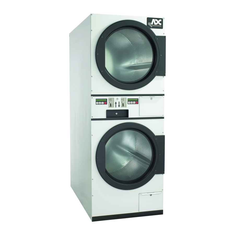
AD-236 Installation Manual
WARNING: For your safety the information
in this manual must be followed to
minimize the risk of fire or explosion and
to prevent property damage, personal
injury or death.
— Do not store or use gasoline or other
flammable vapors and liquids in the
vicinity of this or any other appliance.
— WHAT TO DO IF YOU SMELL GAS:
Do not try to light any appliance.
Do not touch any electrical switch;
do not use any phone in your
building.
Clear the room, building or area of
all occupants.
Immediately call your gas supplier
from a neighbor's phone. Follow
the gas supplier's instructions.
If you cannot reach your gas
supplier, call the fire department.
— Installation and service must be
performed by a qualified installer, service
agency or the gas supplier.
Phase 5 / Gas DSI
AVERTISSEMENT: Assurez-vous de bien
suivre les instructions données dans cette
notice pour réduire au minimum le risque
d'incendie ou d'explosion ou pour éviter
tout dommage matériel, toute blessure ou
la mort.
—Ne pas entreposer ni utiliser d'essence
ni d'autres vapeurs ou liquides
inflammables à proximité de cet
appareil ou de tout autre appareil.
—QUE FAIRE SI VOUS SENTEZ UNE
ODEUR DE GAZ:
Ne pas tenter d'allumer d'appareils.
Ne touchez à aucun interrupteur. Ne
pas vous servir des téléphones se
trouvant dans le bâtiment.
Évacuez la pièce, le bâtiment ou la
zone.
Appelez immédiatement votre
fournisseur de gaz depuis un voisin.
Suivez les instructions du fournisseur.
Si vous ne pouvez rejoindre le
fournisseur de gaz, appelez le service
des incendies.
—L'installation et l'entretien doivent être
assurés par un installateur ou un
service d'entretien qualifié ou par le
fournisseur de gaz.
American Dryer Corporation
88 Currant Road
Fall River MA 02720-4781 USA
Telephone: +1 (508) 678-9000 / Fax: +1 (508) 678-9447
e-mail: techsupport@amdry.com
www.adclaundry.com
ADC Part No. 113047 - 21
Advertisement
Table of Contents

Subscribe to Our Youtube Channel
Related Manuals for American Dryer Corp. AD-236


Summary of Contents for American Dryer Corp. AD-236
- Page 1 AD-236 Installation Manual Phase 5 / Gas DSI AVERTISSEMENT: Assurez-vous de bien WARNING: For your safety the information suivre les instructions données dans cette in this manual must be followed to notice pour réduire au minimum le risque minimize the risk of fire or explosion and d’incendie ou d’explosion ou pour éviter...
- Page 2 The illustrations included in this manual may not depict your particular dryer exactly. Important For your convenience, log the following information: AD-236 (Gas DSI) DATE OF PURCHASE ____________________________________________ MODEL NO. ______________________________ RESELLER’S NAME ________________________________________________________________________________________ Serial Number(s)
- Page 3 WARNING Proposition 65 Use of this product could expose you to substances from fuel combustion that contain chemicals known to the State of California to cause cancer, birth defects and other reproductive harm. In the State of Massachusetts, the following installation instructions apply: Installations and repairs must be performed by a qualified or licensed contractor, plumber, or gasfitter qualified or licensed by the State of Massachusetts.
- Page 4 FOR YOUR SAFETY DO NOT DRY MOP HEADS IN THE DRYER. DO NOT USE DRYER IN THE PRESENCE OF DRY CLEANING FUMES. WARNING UNDER NO CIRCUMSTANCES should the dryer door switches, lint drawer switch, or heat safety circuit ever be disabled. Do not modify this appliance.
-
Page 5: Table Of Contents
Table of Contents SECTION I IMPORTANT INFORMATION ................3 A. Receiving and Handling ....................... 3 B. Safety Precautions ........................4 SECTION II SPECIFICATIONS ..................... 6 A. Specifications ..........................6 SECTION III INSTALLATION PROCEDURES ................8 A. Unpacking/Setting Up ......................... 8 B. - Page 6 SECTION VII ROUTINE MAINTENANCE .................. 31 A. Cleaning ........................... 31 B. Adjustments ..........................32 C. Lubrication ..........................32 SECTION VIII DATA LABEL INFORMATION ................33 A. Data Label ..........................33 SECTION IX TROUBLESHOOTING ................... 35 SECTION X PROCEDURE FOR FUNCTIONAL CHECK OF REPLACEMENT COMPONENTS ..............
-
Page 7: Important Information
SECTION I IMPORTANT INFORMATION A. RECEIVING AND HANDLING The dryer is shipped in a protective stretch wrap cover with protective cardboard corners and top cover (or optional box) as a means of preventing damage in transit. Upon delivery, the dryer and/or packaging, and wooden skid should be visually inspected for shipping damage. -
Page 8: Safety Precautions
B. SAFETY PRECAUTIONS WARNING: For your safety, the information in this manual must be followed to minimize the risk of fire or explosion or to prevent property damage, personal injury, or loss of life. WARNING: The dryer must never be operated with any of the back guards, outer tops, or service panels removed. - Page 9 8. The possible presence of residual quantities of aggressive or decomposed chemicals in the load may produce damage to the machine and harmful fumes. 9. A program should be established for the inspection and cleaning of lint in the burner area, exhaust ductwork, and area around the back of the dryer.
-
Page 10: Specifications
SECTION II SPECIFICATIONS A. SPECIFICATIONS MAXIMUM CAPACITY 30 lb 13.6 kg (DRY WEIGHT) PER POCKET 69.22 cm TUMBLER DIAMETER 27-1/4” TUMBLER DEPTH 30” 76.2 cm 286 L TUMBLER VOLUME 10.1 cu ft PER POCKET TUMBLER/DRIVE MOTOR 1/2 hp 0.373 kW PER POCKET BLOWER/FAN MOTOR 1/2 hp... - Page 11 SPECIFICATIONS ADG-236 (GAS) NOTE: ADC reserves the right to make changes in specifications at any time without notice or obligation. 113047 - 21 www.adclaundry.com...
-
Page 12: Installation Procedures
SECTION III INSTALLATION PROCEDURES Installation should be performed by competent technicians in accordance with local and state codes. In the absence of these codes, the installation must conform to applicable American National Standards: ANSI Z223.1- LATEST EDITION (National Fuel Gas Code) or ANSI/NFPA NO. 70-LATEST EDITION (National Electrical Code) or in Canada, the installation must conform to applicable Canadian Standards: CAN/CGA-B149.1-M91 (Natural Gas) or CAN/CGA-B149.2-M91 (Liquid Propane [L.P.] Gas) or LATEST EDITION (for General Installation and Gas Plumbing) or Canadian Electrical Codes Parts 1 &... -
Page 13: Location Requirements
B. LOCATION REQUIREMENTS Before installing the dryer, be sure the location conforms to local codes and ordinances. In the absence of such codes or ordinances the location must conform with the National Fuel Gas Code ANSI.Z223.1 LATEST EDITION, or in Canada, the installation must conform to applicable Canadian Standards: CAN/CGA-B149.1- M91 (Natural Gas) or CAN/CGA-B149.2-M91 (Liquid Propane [L.P.] Gas) or LATEST EDITION (for General Installation and Gas Plumbing). -
Page 14: Dryer Enclosure Requirements
10. The dryer must be installed with provisions for adequate combustion and make-up air supply. CAUTION: This dryer produces combustible lint and must be exhausted to the outdoors. Every 6 months, inspect the exhaust ducting and remove any lint build up. IMPORTANT: Dryer must be installed in a location/environment, which the ambient temperature remains between 40°... - Page 15 Air supply (make-up air) must be given careful consideration to assure proper performance of each dryer. An unrestricted source of 800 cfm (cubic feet per minute) (22.66 cmm [cubic meters per minute]) is necessary for each dryer. As a general rule, an unrestricted air entrance from the outdoors (atmosphere) of a minimum of 1-1/2 square feet (0.41 square meters) is required for each dryer.
-
Page 16: Exhaust Requirements
E. EXHAUST REQUIREMENTS Exhaust ductwork should be designed and installed by a qualified professional. Improperly sized ductwork will create excessive back pressure which results in slow drying, increased use of energy, overheating of the dryer, and shut down of the burner by the airflow (sail) switches, burner hi-limits, or basket (tumbler) hi-limit thermostats. The dryer must be installed with a proper exhaust duct connection to the outside. - Page 17 NOTE: As per the National Fuel Gas Code, “Exhaust ducts for Type 2 clothes dryers shall be constructed of sheet metal or other noncombustible material. Such ducts shall be equivalent in strength and corrosion resistance to ducts made of galvanized sheet steel not less than 0.0195 inches (26 gauge [0.50 mm]) thick.”...
- Page 18 2. Multiple Dryer (Common) Venting If it is not feasible to provide a separate exhaust duct for each dryer, ducts from individual dryers may be channeled into a “common main duct.” The individual ducts should enter the bottom or the side of the main duct at an angle not more than 45°...
- Page 19 To protect the outside end of the horizontal ductwork from the weather, a 90º elbow bent downward should be installed where the exhaust exits the building. If the exhaust ductwork travels vertically up through the roof, it should be protected from the weather by using a 180º turn to point the opening downward. In either case, allow at least twice the diameter of the duct between the duct opening and nearest obstruction.
-
Page 20: Electrical Information
F. ELECTRICAL INFORMATION 1. Electrical Requirements It is your responsibility to have ALL electrical connections made by a properly licensed and competent electrician to assure that the electrical installation is adequate and conforms to local and state regulations or codes. In the absence of such codes, ALL electrical connections, materials, and workmanship must conform to the applicable requirements of the National Electrical Code ANSI/NFPA NO. - Page 21 SINGLE-PHASE (1Ø) ELECTRICAL CONNECTION LEADS Black White Green Positive Neutral Ground Providing local codes permit, power to the dryer can be made by use of a flexible U.L. listed power cord or pigtail (wire size must conform to the rating of the dryer), or the dryer can be hard wired directly to the service breaker panel.
- Page 22 5. Electrical Service Specifications ELECTRICAL SERVICE SPECIFICATIONS (PER DRYER) IMPORTANT: 208 VAC AND 230/240 VAC ARE NOT THE SAME. When ordering, specify exact voltage. NOTES: When fuses are used they must be dual element, time delay, current limiting, class RK1 or RK5 ONLY . Calculate/determine correct fuse value, by applying either local and/or National Electrical Codes to listed appliance amp draw data.
-
Page 23: Gas Information
G. GAS INFORMATION It is your responsibility to have ALL plumbing connections made by a qualified professional to assure that the gas plumbing installation is adequate and conforms to local and state regulations or codes. In the absence of such codes, ALL plumbing connections, materials, and workmanship must conform to the applicable requirements of the National Fuel Gas Code ANSI Z223.1-LATEST EDITION, or in Canada, the Canadian Installation Codes CAN/CGA-B149.1-M91 (Natural Gas) or CAN/CGA-B149.2-M91 (Liquid Propane [L.P.] Gas) or LATEST... - Page 24 2. Technical Gas Data a. Gas Specifications TYPE OF GAS NATURAL LIQUID PROPANE Manifold Pressure* 3.5 inches W.C. 8.7 mb 10.5 inches W.C. 26.1 mb In-Line Pressure 6.0 - 12.0 inches W.C. 14.92 - 29.9 mb 11.0 inches W.C. 27.4 mb Shaded areas are stated in metric equivalents * Measured at gas valve pressure tap when the gas valve is on.
- Page 25 3. Piping Connections ALL components/materials must conform to National Fuel Gas Code Specifications ANSI Z223.1-LATEST EDITION, or in Canada, CAN/CGA-B149.1-M91 (Natural Gas) or CAN/CGA-B149.2-M91 (Liquid Propane [L.P.] Gas) or LATEST EDITION (for General Installation and Gas Plumbing), as well as local codes and ordinances and must be done by a qualified professional.
- Page 26 American Dryer Corp. 113047 - 21...
-
Page 27: Preparation For Operation/Start-Up
H. PREPARATION FOR OPERATION/START-UP The following items should be checked before attempting to operate the dryer: 1. Read ALL “CAUTION,” “WARNING,” and “DIRECTION” labels attached to the dryer. 2. Check incoming supply voltage to be sure that it is the same as indicated on the dryer data label affixed to the left sidewall area behind the middle access (control) door. - Page 28 3) Start the dryer by pressing the desired setting (i.e., “LO” [low] selection for upper basket [tumbler]). The light emitting diode (L.E.D.) display(s) will now read the selection (setting) made and the amount of time vended (i.e., “LO 10”). NOTE: The dryer can be stopped at any time by opening the main door. To restart dryer, shut the main door and press the desired setting.
-
Page 29: Shutdown Instructions
3. Make a complete operational check of ALL the operating controls to ensure that the timing is correct and that the temperatures are set properly. 4. Make a complete operational check of ALL safety-related circuits (i.e., door switches, hi-limit thermostats, sail switches, and basket [tumbler] safety thermostats, etc.). -
Page 30: Operating Instructions
SECTION IV OPERATING INSTRUCTIONS A. STARTING THE DRYER The dryer is available for use when the applicable (top or bottom basket [tumbler]) microprocessor controller (computer) light emitting diode (L.E.D.) display reads the amount needed to start the dryer (i.e., “25”). Once the load has been put into the dryer and the main door is closed, start the dryer as follows: 1. - Page 31 NOTE: When a cycle is interrupted by opening the main door, cycle time will continue to count downward, regardless if the door is open or closed until a keypad selection is made. 2) Selection (setting) changes can be made at any time during the drying cycle by opening and closing the main door and then making a new selection.
-
Page 32: Service/Parts Information
SECTION V SERVICE/PARTS INFORMATION A. SERVICE 1. Service must be performed by a qualified trained technician, service agency, or gas supplier. If service is required, contact the reseller from whom the ADC equipment was purchased. If the reseller cannot be contacted or is unknown, contact the ADC Service Department for a reseller in your area. -
Page 33: Warranty Information
SECTION VI WARRANTY INFORMATION A. RETURNING WARRANTY CARDS 1. Before any dryer leaves the ADC factory test area, a warranty card is placed on the back side of the main door glass. These warranty cards are intended to serve the customer where we record the individual installation date and warranty information to better serve you should you file a warranty claim. - Page 34 2. Each part must be tagged with the following information: a. Model number and serial number of the dryer from which part was removed. b. Nature of failure (be specific). c. Date of dryer installation. d. Date of part failure. e.
-
Page 35: Routine Maintenance
SECTION VII ROUTINE MAINTENANCE A. CLEANING A program and/or schedule should be established for periodic inspection, cleaning, and removal of lint from various areas of the dryer, as well as throughout the ductwork system. The frequency of cleaning can best be determined from experience at each location. -
Page 36: Adjustments
90 DAYS 1. Remove lint from around basket (tumbler), drive motors, and surrounding areas. 2. Remove lint from gas valve burner area with a dusting brush or vacuum cleaner attachment. 3. Clean any lint accumulation in and around both the blower and drive motor casing openings. NOTE: To prevent damage, avoid cleaning or touching the direct spark ignitor assembly. -
Page 37: Data Label Information
SECTION VIII DATA LABEL INFORMATION A. DATA LABEL Contact American Dryer Corporation When contacting American Dryer Corporation, certain information is required to insure proper service/parts information from ADC. This information is on the data label that is located on the left sidewall area behind the middle access (control) door. - Page 38 CE LABEL AGA LABEL THE DATA LABEL 1. Model Number – This describes the style of dryer and type of heat (gas, electric, or steam). 2. Serial Number – Allows the manufacturer to gather information on your particular dryer. 3. Type of Heat – This describes the type of heat for your particular dryer, gas (either natural gas or L.P.
-
Page 39: Troubleshooting
SECTION IX TROUBLESHOOTING WARNING: YOU MUST DISCONNECT AND LOCKOUT THE ELECTRIC SUPPLY AND THE GAS SUPPLY BEFORE ANY COVERS OR GUARDS ARE REMOVED FROM THE MACHINE TO ALLOW ACCESS FOR CLEANING, ADJUSTING, INSTALLATION, OR TESTING OF ANY EQUIPMENT PER OSHA (Occupational Safety and Health Administration) STANDARDS. The information provided will help isolate the most probable component(s) associated with the difficulty described. - Page 40 D. The dryer operates for a few minutes, and with the microprocessor controller (computer) motor L.E.D. indicator dot on the motor stops, and then after a period of time restarts on its own... 1. Motor is overheating and tripping out on its internal overload... a.
- Page 41 H. Microprocessor controller (computer) L.E.D. display reads “SEFL”... The “SEFL” display condition indicates a rotational sensor circuit failure which means that there is a fault somewhere in the basket (tumbler) rotation detection circuit...or...the microprocessor controller (computer) program related to this circuit (PL01) is set incorrectly in the active mode (“SEn”) where the dryer is not equipped with the optional rotation sensor and should be set in the nonactive mode (“nSEN”).
- Page 42 L. Heating unit is not operating (no heat)...basket (tumbler) is turning, microprocessor controller (computer) heat indicator dot is on but “HEAT” output L.E.D. is not... 1. Failed microprocessor controller (computer). M. Gas heating unit is not operating (no heat)...both microprocessor controller (computer) heat indicator dot and “HEAT”...
- Page 43 Dryer operates, but is taking too long to dry... 1. Exhaust ductwork run is too long or is undersized...back pressure must be no less than 0 and cannot exceed 0.3 inches (0.74 mb) water column. 2. Low and/or inconsistent gas pressure. 3.
-
Page 44: Procedure For Functional Check Of Replacement Components
SECTION X PROCEDURE FOR FUNCTIONAL CHECK OF REPLACEMENT COMPONENTS 1. Microprocessor Controller (Computer) Board a. Upon completing installation of the replacement microprocessor controller (computer) board, reestablish power to the dryer. b. Start the drying cycle. c. Verify that the motors and the heat indicator dots, in the microprocessor controller (computer) light emitting diode (L.E.D.) display are on. - Page 45 e. Open main door. The dryer must stop and ALL output indicator lights on the back side of the microprocessor controller (computer) board must go out. f. Try to restart the dryer with the main door open. g. The microprocessor controller (computer) board’s light emitting diode (L.E.D.) display must read “DOOR.” h.
- Page 46 3. For Direct Spark Ignition (DSI) System Models Manufactured With ADC Module Part No. 882627 a. Upon completing installation of the replacement DSI module, reestablish power to the dryer. b. Starting the drying cycle. c. The ignition DSI module’s light emitting diode (L.E.D.) indicator will light “red”...
-
Page 47: Burner/Basket (Tumbler) Hi-Limit Manual Reset Instructions
SECTION XI BURNER/BASKET (TUMBLER) HI-LIMIT MANUAL RESET INSTRUCTIONS Both the top and bottom basket (tumbler) of this dryer is equipped/manufactured with a manual reset burner hi-limit and manual reset basket (tumbler)/lint chamber hi-limit thermostat. If either manual reset hi-limit thermostat is open prior to the start of the drying cycle, or during the drying cycle, the dryer will not recognize the open (tripped) state of the applicable basket (tumbler)/hi-limit thermostat and will start or continue through the drying cycle with no heat. - Page 48 ADC Part No. 113047 21 - 11/13/15...
Need help?
Do you have a question about the AD-236 and is the answer not in the manual?
Questions and answers