
Related Manuals for Mosa DPiL Series


Summary of Contents for Mosa DPiL Series
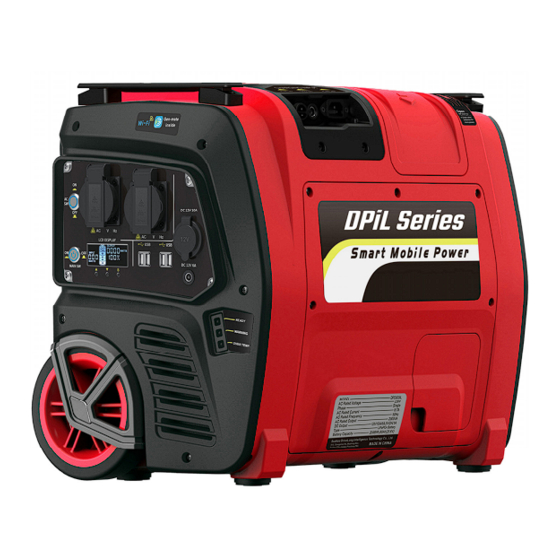
- Page 1 OWNER'S MANUAL Smart Mobile POWER DPiL Series DP500iL / DP1000iL / DP1500iL/ DP2000iL VER1.2-20201010...
-
Page 2: Table Of Contents
CONTENT 1. UNIT DESCRIPTION ................- 3 - 1.1 COMPONENTS IDENTIFICATION ..........- 3 - 1.2 OUTPUT PANEL ................- 4 - 1.3 CHARGING INPUT PANEL............. - 7 - 1.4 BATTERY CONNECTOR ..............- 8 - 2. - Page 3 INTRODUCTION Congratulations on your selection of a marvelous mobile power. This manual will provide you with a good basic understanding of the safe operation and maintenance of this machine, please read it carefully. Read this manual carefully before operating this mobile power. This manual should stay with this generator if it is sold.
-
Page 4: Unit Description
1. UNIT DESCRIPTION 1.1 COMPONENTS IDENTIFICATION (1). Output Panel: Location of mobile power controls and output receptacles. (2). Charging Input Panel: Location of mobile power charging input receptacles. (3). Maintenance Cover: Remove the cover to install or replace battery in the mobile power. (4). -
Page 5: Output Panel
Connector before charging or operating the mobile power. 1.2 OUTPUT PANEL ‐ 4 ‐ ... - Page 6 (1). AC Switch: This switch turns ON or OFF AC output of the mobile ‐ 5 ‐ ...
- Page 7 power. (2). AC Receptacle: AC output receptacles for connecting AC devices. (3). Main Switch: This switch turns ON or OFF DC output of the mobile power, and AC Switch is available only after the main switch is turned (4). Cigarette Lighter Receptacle: 12V DC output receptacle for cigarette lighter plug.
-
Page 8: Charging Input Panel
Battery is under voltage. Battery is over voltage. (14). Over Temperature: The light comes ON and flashes when the temperature in the mobile power is over high. 1.3 CHARGING INPUT PANEL (1). PV Charging Input: Charge the mobile power from solar panels. (2). -
Page 9: Battery Connector
1.4 BATTERY CONNECTOR You need to connect the battery connector 2 before charging or using the mobile power: (1). Open the connector cover 1. (2). Connect the battery connector 2, otherwise the mobile power cannot be charged or used. 2. -
Page 10: Pv Charging Input
2.1 PV CHARGING INPUT Loosen ‐ 9 ‐ ... -
Page 11: Ac Charging Input
You can charge the mobile power from solar panels as follows: (1). Remove the cover 1 from PV charging port 2. (2). Connect PV charging port 2 to MC4 port 5 of solar panels 4 by PV charging cable 3, which can be found in the packing box. 2.2 AC CHARGING INPUT ‐ 10 ‐ ... -
Page 12: Dc Charging Input
You can charge the mobile power from wall outlet or other AC source as follows: Connect AC charging port 1 to any wall receptacle by the AC charging cable 2, which can be found in the packing box. 2.3 DC CHARGING INPUT You can charge the mobile power from car or any 12V/24V source as follows: Connect DC charging port 1 to cigarette lighter receptacle of 12V or... -
Page 13: Operating The Mobile Power
3. OPERATING THE MOBILE POWER 3.1 DC OPERATION You can use the DC output from the mobile power as follows: (1). Push the main switch 6 to "ON" position. (2). Receptacle 2 and 5 all are 12V DC output port, according to the plug type of 12V DC electric devices to choose suitable one to connect. -
Page 14: Ac Operation
will shut off. 3.2 AC OPERATION You can use the AC output from the mobile power as follows: (1). Push the main switch 6 to "ON" position. (2). Push the AC switch 7 to "ON" position. (3). Make sure the ready LED 8 comes on. (4). -
Page 15: Lcd Display
Do not operate with wet hand. Do not operate by children without supervision. Do not expose the mobile power to rain, moisture or snow. NOTE Be sure all electric devices including the lines and plug connections are in good condition before connection to the mobile power. - Page 16 ▼ buttons ▲/ /S. The built-in LCD Display can indicate some important information: Battery icon: When the mobile power is charging, the battery segments in the LCD screen will blink. The mobile power is fully charged when all battery segments stop blinking and remain solid.
- Page 17 Shows remaining charging hours of the battery while charging. Shows remaining operation hours of the battery while discharging. POWER icon will show when the Gen-mate unit (optional equipment) inside the mobile power is operating normally. Wi-Fi icon will flash slowly when the mobile power equipped with Gen-mate unit (optional equipment) is connected to the Gen-mate APP in Smartphone by Wi-Fi.
-
Page 18: Replace The Battery
5. REPLACE THE BATTERY Read the instructions before you begin, and make sure you have the tools and skills required. Shut off the mobile power before starting to replace the battery. If you are not familiar with maintenance work, have an authorized dealer do it for you. - Page 19 Loosen Loosen (1). Loosen five screws and remove the maintenance cover 1. (2). Disconnect the battery connector 2. (3). Loosen the screws 5, 6 with a box spanner 3 to remove the battery baffle plate 4. The spanner 3 can be found in the packing box. (4).
-
Page 20: Install The Battery
5.2 INSTALL THE BATTERY 5.2.1 BIND THE BATTERY (1). Take out the battery bandage 1 from the packing box. (2). Place the bandage 1 at the side of the battery 2, as shown in the figure above. (3). Bind the bandage 1 around the battery 2. (4). -
Page 21: Reinstall The Battery Into The Mobile Power
5.2.2 REINSTALL THE BATTERY INTO THE MOBILE POWER Tighten (1). Hold the battery 1 and put the battery 1 totally into the mobile power. (2). Insert bottom end of baffle plate 2 into the bottom hole on the battery support, and then tighten the screw 3, 4 with a box spanner 5, which can be found in the packing box. -
Page 22: Connect The Battery
5.2.3 CONNECT THE BATTERY Screws Tighten (1). Take out the battery connector 3 from the connector window 4 on the maintenance cover 1. (2). Insert the three bulge parts at the bottom of the maintenance cover 1 into the three installation holes at the bottom of the main case 2. -
Page 23: Transportation And Storage
(4). Make sure the battery connector 3 is connected securely together. (5). Put the battery connector 3 into the right place in the mobile power through the connector window 4 as shown in the figure above. (6). Put on the connector cover 5 closely. 6. -
Page 24: Output Protection
code 004 will show in the LCD screen. Charge the battery immediately. Battery Over Voltage Protection: When the battery voltage is too higher, the charging input will automatically shut down. Fault code 008 will show in the LCD screen. Stop charging the battery immediately and contact an authorized dealer. -
Page 25: Trouble Shooting
8. TROUBLE SHOOTING No DC Output Push the main switch to the Is the main switch OFF? ON position. Is the battery power too low? Charge the battery. Turn electrical Does the over temperature appliance connected to the indicator on the screen/panel or power station, and put the APP go on? power station in a cool place... - Page 26 Is there any fault on the DC Adjust replace electrical appliance? appliance. Contact with an authorized dealer. No AC Output Push the main switch to the Is the main switch OFF? ON position. Push the AC switch to the ON Is the AC switch OFF? ...
- Page 27 Is the AC output overloaded? Reduce loads and push the (The warning light on the panel AC switch to reset module. flashes) Check and correct condition of Is the AC electrical device short any extension cords and all circuit? (The warning light on items being powered, then the panel flashes) push the AC switch to reset...
-
Page 28: Specifications
9. SPECIFICATIONS DPiL SERIES SPECIFICATIONS Model DP500iL DP1000iL DP1500iL DP2000iL Rated Power 500VA 1000VA 1500VA 2000VA Peak Power 1000VA 2000VA 3000VA 4000VA Dimensions 530mm(20.9 in)X320mm(12.6 in)X430mm(16.9 in) Weight 27kg (60 lbs) 34kg (75 lbs) 34kg (75 lbs) 36kg (79 lbs) - Page 29 NOTE (1).The Anderson port is only for DP500iL. (2).The output specifications are based on the standard ambient temperature: 25℃. ‐ 28 ‐ ...
- Page 30 More power More smart EASY POWER WITH YOU ...
Need help?
Do you have a question about the DPiL Series and is the answer not in the manual?
Questions and answers