
Related Manuals for Mosa GE 55 PSX


Summary of Contents for Mosa GE 55 PSX
- Page 1 GE 55 PSX-PMSX GE 65 PSX-PMSX 1 1 1 2 840589003 - GB USE AND MAINTENANCE MANUAL © MOSA - 19/11/12 84058M00 preparato da UPT approvato da DITE...
-
Page 3: Description Of The Machine
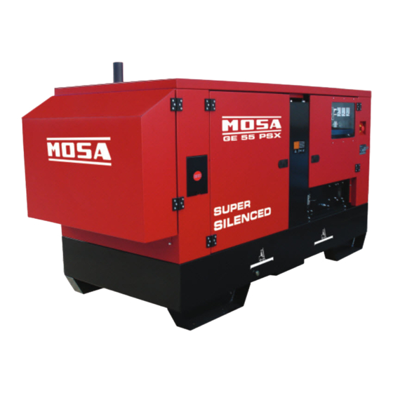
DESCRIPTION OF THE MACHINE GE 55 PSX-PMSX GE 65 PSX-PMSX REV.0-11/12 Main Characteristics of the unit: • Three-phase electric power 51 kVA (40.8 kW)/ 400 V / 73.6 A (GE55P), 66 kVA (52.8 kW) / 400 V / 95A (GE65P) • Perkins Diesel engine 1103A - 33TG1 (GE55P), Perkins 1103A - 33TG2 (GE65P) • Brushless synchronous alternator • Tank of 102l with autonomy of 12.5 h (GE55P) - 10 h (GE65P) • Dimensions / weight: 2490x1030x1480 / 1200 Kg (GE55P) - 1200 Kg (GE65P) • Noise level at 7m 66dBA (GE55P) - 67dBA (GE65P) • Prepared for automatic start unit • Prepared for remote start/stop. MUFFLER CONNECTOR CONNECTOR FOR REMOTE START The assembly has 4 doors which facilitate ordinary engine maintenance. On the side of the air intake, under the apertures, there is a cover fixed with 4 screws, the removal of which makes it possible to check the alternator pick-up and/or the PMG if mounted (Permanent Magnets). Under the front of the machine there is a protected aperture which... - Page 5 · Competent support in the solution of problems; ofthe International Certification Network IQNet, · Information and training in the correct applicatio- awarded the official approval to MOSA after an- nand use of the products to assure the security examination of its operations at the head office ofthe operator and protect the environment;...
- Page 6 Index GE 55 PSX-PMSX GE 65 PSX-PMSX REV.0-11/12 M 0 DESCRIPTION OF THE MACHINE M 01 QUALITY SYSTEM M 1.01 COPYRIGHT M 1.1 NOTES M 1.4 CE MARK M 1.4.1 DECLARATION OF CONFORMITY M 1.5 TECHNICAL DATA M 2 - 2.1 SYMBOLS AND SAFETY PRECAUTIONS M 2.5 INSTALLATION AND ADVICE BEFORE USE M 2.6 INSTALLATION AND ADVICE M 2.7 INSTALLATION M 3 UNPACKING M 4.2 TRANSPORT AND DISPLACEMENTS M 6.8 ASSEMBLY: CTL 45 M 20 PREPARING THE UNIT M 21 START AND STOP...
- Page 7 (see page M1.1). All rights are reserved to said Company. It is a property logo of MOSA division of B.C.S. S.p.A. All other possible logos contained in the documen- tation are registered by the respective owners.
-
Page 8: Notes About The Manual
Notes REV.0-10/02 INFORMATION INFORMATION OF GENERAL TYPE In the envelope given together with the machine and/or Dear Customer, set you will find: the manual for Use Maintenance and We wish to thank you for having bought a high quality set. Spare Parts, the manual for use of the engine and the tools (if included in the equipment), the guarantee (in the Our sections for Technical Service and Spare Parts will... - Page 9 CE MARK REV.5-03/11 Any of our product is labelled with CE marking attesting its conformity to appliable directives and also the fulfillment of safety requirements of the product itself; the list of these directives is part of the declaration of conformity included in any machine standard equipment. Here below the adopted symbol: CE marking is clearly readable and unerasable and it can be either part of the data-plate.
-
Page 10: Dichiarazione Di Conformita
Dichiarazione conformità Konformitätserklärung Declaration of conformity Declaración de conformidad 1.4.1 Déclaration de conformité Declaração de conformidade REV.0-06/10 BCS S.p.A. Stabilimento di Cusago, 20090 (MI) - Italia V.le Europa 59 Sede legale: Tel.: +39 02 903521 Via Marradi 1 Fax: +39 02 90390466 20123 Milano - Italia DICHIARAZIONE DI CONFORMITA' Déclaration de Conformité... - Page 11 Technical data GE 55 PSX-PMSX REV.0-11/12 The generating set GE 55 is a unit which transforms the mechanical energy, generated by endothermic engine, into electric energy, through an alternator. Is meant for industrial and professional use, powered by an endothermic engine; it is composed of various main parts such as: engine, alternator, electric and electronic controls, the fairing or a protective structure. The assembling is made on a steel structure, on which are provided elastic support which must damp the vibrations and also eliminate sounds which would produce noise. Technical data GE 55 PSX GE 55 PMSX GENERATOR Stand-by three-phase power 51 kVA (40.8 kW)/ 400 V / 73.6 A PRP three-phase power 46 kVA (36.8 kW)/ 400 V / 66.4 A Single-phase power 17 kVA / 230 V / 73.9 A...
- Page 12 Technical data GE 65 PSX - PMSX 1.5.1 REV.0-11/12 The generating set GE 65 is a unit which transforms the mechanical energy, generated by endothermic engine, into electric energy, through an alternator. Is meant for industrial and professional use, powered by an endothermic engine; it is composed of various main parts such as: engine, alternator, electric and electronic controls, the fairing or a protective structure. The assembling is made on a steel structure, on which are provided elastic support which must damp the vibrations and also eliminate sounds which would produce noise. Technical data GE 65 PSX GE 65 PMSX GENERATOR Stand-by three-phase power 66 kVA (52.8 kW) / 400 V / 95.2A PRP three-phase power 60 kVA (48 kW) / 400 V / 86.6 A Single-phase power 22 kVA / 230 V / 95.6A Frequency...
-
Page 13: Symbols In This Manual
SYMBOLS AND SAFETY PRECAUTIONS REV.0-11/99 SYMBOLS IN THIS MANUAL SAFETY PRECAUTIONS DANGEROUS The symbols used in this manual are designed to call your attention to important aspects of the operation of the machine as well as potential hazards and dangers This heading warns of an immediate danger for persons for persons and things. -
Page 14: Symbols And Safety Precautions
SYMBOLS AND SAFETY PRECAUTIONS REV.2-06/10 SYMBOLS PROHIBITIONS No harm for persons Use only with safety clothing - STOP - Read absolutely and be duly attentive It is compulsory to use the personal protection means given in equip- ment. Use only with safety clothing - Read and pay due attention It is compulsory to use the personal protection means given in equipment. - Page 15 INSTALLATION AND ADVICE BEFORE USE REV.0-06/00 The installation and the general advice concerning the operations, are finalized to the correct use of the ma- chine, in the place where it is used as generator group and/or welder. Stop engine when fueling Do not touch electric devices if you are barefoot or with wet Do not smoke, avoid flames, sparks or electric tools when fueling.
-
Page 16: Gasoline Engines
INSTALLATION AND ADVICE REV.1-06/07 Check that the air gets changed completely and the hot INSTALLATION AND ADVICE BEFORE USE air sent out does not come back inside the set so as to cause a dangerous increase of the temperature. GASOLINE ENGINES Use in open space, air swept or vent exhaust gases, which contain the deathly carbone oxyde, far from the work area. - Page 17 Installazione Luftzirculation Installation Instalación GE 55 PSX-PMSX Installation GE 65 PSX-PMSX REV.0-02/07...
- Page 18 UNPACKING REV.1-02/04 NOTE + Be sure that the lifting devices are: correctly mounted, adequate for the weight of the machine with it’s pack- aging, and conforms to local rules and regulations. When receiving the goods make sure that the product has not suffered damage during the transport, that there has not been rough handling or taking away of parts contained inside the packing or in the set.
- Page 19 TRANSPORT AND DISPLACEMENTS COVERED UNITS AND SKID REV.1-06/10 NOTE Transportation must always take place with the engine off, electrical cables and starting battery disconnected and fuel tank empty. Be sure that the lifting devices are: correctly mounted, adequate for the weight of the machine with it’s packaging, and conform to local rules and regulations.
- Page 20 CTL 35 - 45 - 50 - 95 ASSEMBLY REV.1-03/06 ATTENTION The CTL accessory cannot be removed from the machine and used separately (actioned manually or following vehicles) for the transport of loads or anyway for used different from the machine movements. TRAILERS The machines provided for assembling the CTL accessory (slow towing trolley) can be towed up to a maximum speed of 40 Kms/hour on asphalted surfaces.
- Page 21 Avoid accidentally spilling fuel. Clean RECOMMENDED OIL any eventual leaks before starting up MOSA recommends selecting AGIP engine oil. motor. Refer to the label on the motor for the recommended products. Refill the tank with good quality diesel fuel, such as automobile type diesel fuel, for example.
-
Page 22: Cooling Liquid
Set-up for operation Water cooled systems REV.1-02/11 GROUNDING CONNECTION COOLING LIQUID ATTENTION The grounding connection to an earthed installation is obligatory for all models equipped with a diffe- Do not remove the radiator tap with the rential switch (circuit breaker). In these groups the motor in operation or still hot, as the generator star point is generally connected to the liquid coolant may spurt out and cause... - Page 23 START AND STOP (EP6) REV.0-02/06 Check daily The EAS controls the starting as well as the stop of the engine. Follow attentively the instructions reported in the EAS manual. In these conditions the EP6 has the only function to measure the electric values, NOTE hour-meter, etc.
- Page 24 CONTROLS LEGENDE REV.2-07/08 Hydraulic oil level light Exclusion indicating light PTO HI Battery voltmeter Welding socket ( + ) Auxiliary current push button Remote control socket Welding socket ( - ) Fuel level light Button indicating light 20 l/1' PTO HI Earth terminal E.A.S. PCB Commutator/switch, serial/parallel A.C. socket Control unit for generating sets QEA Thermal-magnetic circuit breaker Accelerator lever Selection push button 20 l/1' PTO HI Ground fault interrupter ( 30 mA ) Feed pump Water temperature indicator Engine control unit and economiser 48V D.C. socket Engine air filter Ammeter Oil level dipstick Frequency meter Engine oil reservoir cap Frequency rpm regulator 24A Hydraulic oil reservoir cap Voltmeter regulator 24B Water filling cap Fuse Fuel prefilter Stop switch Fuel tank cap Warning light, high temperature Muffler Arc-Force selector...
- Page 25 Comandi Bedienelemente Controls Mandos GE 55 PSX-PMSX Commandes REV.0-02/07...
- Page 26 Comandi Bedienelemente Controls Mandos GE 65 PSX-PMSX 31.1 Commandes REV.0-02/07...
- Page 27 Using the generator REV.3-11/11 are the same. WARNING + In the absence of a load, the values for voltage and frequency can be greater than their nominal values. See It is absolutely forbidden to connect the unit sections on VOLTAGE and FREQUENCY. to the public mains and/or another electrical power source .
- Page 28 Using the generator REV.1-09/05 The frequency, and therefore the number of motor SINGLE-PHASE LOADS revolutions, is maintained constant by the motor’s speed Power to monophase utilities by means of three-phase regulation system. generators requires some operating limitations. Generally, this regulator is of a mechanical type and - In single-phase operation, the declared voltage presents a droop from no-load to nominal load which tolerance can no longer be maintained by the regulator...
-
Page 29: Differential Switch
Using the generator REV.1-09/05 DIFFERENTIAL SWITCH USAGE WITH EAS AUTOMATIC START-UP PANEL The differential switch or differential relay guarantee The electricity-generating group in combination with the protection against indirect contacts due to malfunction EAS automatic start-up panel forms a unit for distributing currents towards the ground. -
Page 30: Accessory Use
ACCESSORY USE REMOTE CONTROL TC2 / TC2/50 REV.1-06/05 PUSH AND SCREW TIGHT The remote control device for regulating the welding current is connected to the front panel by means of a multipole connector. To regulate the current from the TC2 / TC2/50, move the switch (7), located above the multipole connector (8), to "ON"... - Page 31 PROTECTIONS INSULATION MONITORING 39.10 REV..0-05/01 USE OF SRI/D3 MODEL NOTE - To vary the regulation call our Technical Assist- ance Department Don not intervene on the setting of the protection - The warning light ON shows that the device is switch.
-
Page 32: Earth Leakage Relay
BEWARE: this operation is allowed only under the responsibility of personnel able to activate different solutions to ensure electrical protection of the system powered by the gen-set. USE OF THE DER3 / 0D MODEL (MOSA SET UP) 1) Manual reset 2) Regulation of intervention time: INST (instantaneous) 3) Regulation of fault current: 30 mA 4) Output relay: N.De... -
Page 33: Front Panel
PROTECTIONS EP6 ENGINE PROTECTION 39.12 REV.1-03/11 FRONT PANEL C) - In order to cancel the AUTO operating mode, push the AUTO pushbutton (the yellow Led will 4 digits DISPLAY turn OFF) or turn the KEY-SWITCH to OFF. [UP DOWN] Once in AUTO, the EP6 waits for a REMOTE Button START activation (see section 7.0). -
Page 34: Operating Messages
PROTECTIONS EP6 ENGINE PROTECTION 39.12. REV.1-03/11 5.0 LEDs for visual indication 4.0 ALARM messages The EP6 features two LEDs (see section 10.0) to The alarms are displayed by means of messages. indicate the following conditions: In case of alarm consult your Generating Set manu- facturer. - Page 35 PROTECTIONS EP6 ENGINE PROTECTION 39.12. REV.0-10/05 Display Parameter [Default] [P.0] Remote Start Delay Timing (Input #7) [ 1"] Range: 1-59 secs or 1-15 mins Seconds or minutes of continuous REMOTE START command to initiate the auto- matic engine start (see section 7.0 and [P20] in this section). [P.1] Remote Stop Delay Timing (Input #7) [ 1"] Range: 1-59 secs or 1-15 mins...
- Page 36 PROTECTIONS EP6 ENGINE PROTECTION 39.12. REV.1-03/11 [P.17] Alarm Output Timing [ 1'] [inh.] 1-59 secs 1-15 mins and [cont]. Time-out of the alarm output. The code [cont] disables the time-out, and the alarm remains energized until the OFF operating mode is selected.
-
Page 37: Remote Start Switch
PROTECTIONS EP6 ENGINE PROTECTION 39.12. REV.1-03/11 7.0 REMOTE START The EP6 will start the engine after the programmed The EP6 features REMOTE START only in AUTO number of days and the engine will run for the pro- operating mode. grammed time. To determine how the Automatic To operate the REMOTE START, follow the instruc- Periodic Test is programmed enter the Reading tions. -
Page 38: Troubleshooting
Diesel engine 40.2 Troubleshooting REV.3-07/06 Problem Possible cause Solution ENGINE The motor does not start up 1) Start-up switch (I6) (where it is assembled) in 1) Check position incorrect position 2) Emergency button (L5) pressed 2) Unblock 3) Preheating (where it is assembled) 3) Lacking or insufficient preheating phase for sparkplugs. - Page 39 Troubleshooting Diesel engine 40.2. REV.4-03/11 Problem Possible cause Solution GENERATOR Absence of output voltage Voltage switch in position 0 Check position Voltage switch faulty Check connections and working of the switch, repair or replace Protection tripped due to overload Check the load connected and diminish Differential protection device tripped.
- Page 40 MAINTENANCE REV.0-06/10 WARNING ● Have qualified personnel do maintenance and troubleshooting work. ● Stop the engine before doing any work inside the machine. If for any reason the machine must be operated while working inside, pay at- tention moving parts, hot parts (exhaust manifold and muffler, etc.) electrical parts which may be unprotected when the machine is open.
-
Page 41: Maintenance
43.1 MAINTENANCE REV.0-09/05 ATTENTION Maintenance operations on the electricity-generating group prearranged for automatic operation must be carried out with the panel in RESET mode. Maintenance operations on the installation’s electrical panels must be carried out in complete safety by cutting off all external power sources: ELECTRICAL POWER, GROUP and BATTERY. -
Page 42: Gasoline Engine
STORAGE REV.0-06/07 In case the machine should not be used for more than 30 days, make sure that the room in which it is stored presents a suitable shelter from heat sources, weather changes or anything which can cause rust, corrosion or damages to the machine. - Page 43 CUST OFF REV.0-06/07 Have qualified personnel disassemble the In case of necessity for first aid and fire prevention, machine and dispose of the parts, including the see page M2.5. oil, fuel, etc., in a correct manner when it is to be taken out of service.
-
Page 44: Installation
Dimensioni Abmessungen Dimensions Dimensiones GE 55 PSX-PMSX Installation GE 65 PSX-PMSX REV.0-02/07... -
Page 45: Electrical System Legende
ELECTRICAL SYSTEM LEGENDE REV.9-06/11 : Alternator : Stop push-button : Choke button : Wire connection unit : Ignition coil : Switch CC/CV : Capacitor : Spark plug : Connector – wire feeder : G.F.I. : Range switch : 420V/110V 3-phase transformer : Welding PCB transformer : Oil shut-down button : Switch IDLE/RUN : Fuse : Battery charge diode : Hz/V/A analogic instrument : 400V 3-phase socket : Relay : EMC filter : 230V 1phase socket : Resistor : Wire feeder supply switch : 110V 1-phase socket : Sparkler reactor : Wire feeder socket : Socket warning light : Output power unit : DSP chopper PCB : Hour-counter : Electric siren : Power chopper supply PCB : Voltmeter : E.P.4 engine protection : Switch and leds PCB : Welding arc regulator : Engine control PCB W6 : Hall sensor... - Page 46 Stromlaufplan Schema elettrico Electric diagram Esquema eléctrique GE 55 PSX-PMSX 61.1 GE 65 PSX-PMSX Schema electriques REV.0-11/12...
- Page 47 Stromlaufplan Schema elettrico Electric diagram Esquema eléctrique GE 55 PSX-PMSX 61.2 GE 65 PSX-PMSX Schema electriques REV.0-02/07...
- Page 48 Schema elettrico Stromlaufplan Electric diagram Esquema eléctrique GE 55 PSX-PMSX 61.3 Schema electriques REV.0-02/07...
- Page 49 Stromlaufplan Schema elettrico Electric diagram Esquema eléctrique GE 65 PSX-PMSX 61.4 Schema electriques REV.0-02/07...
- Page 50 Schema elettrico Stromlaufplan Electric diagram Esquema eléctrique GE 55 PSX-PMSX 61.5 Schema electriques GE 65 PSX-PMSX REV.0-11/12...
- Page 51 Schema elettrico Stromlaufplan Electric diagram Esquema eléctrique GE 55 PSX-PMSX 61.6 Schema electriques GE 65 PSX-PMSX REV.0-07/07...
- Page 52 Schema elettrico Stromlaufplan Electric diagram Esquema eléctrique GE 55 PSX-PMSX 61.7 Schema electriques GE 65 PSX-PMSX REV.0-07/07...
- Page 54 MOSA div. della BCS S.p.A. Stabilimento di Viale Europa, 59 20090 Cusago (MI) Italia Tel. + 39 - 0290352.1 Fax + 39 - 0290390466...
Need help?
Do you have a question about the GE 55 PSX and is the answer not in the manual?
Questions and answers