Mosa MAGIC WELD 200 Use And Maintenance Manual
Hide thumbs
Also See for MAGIC WELD 200:
- Use and maintenance manual (39 pages) ,
- Use and maintenance manual (48 pages)
Table of Contents
Advertisement
Quick Links
USE AND MAINTENANCE MANUAL
TRANSLATION OF THE ORIGINAL INSTRUCTIONS – ENGLISH
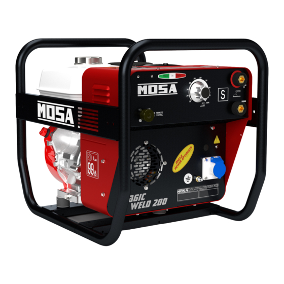
MAGIC WELD 200
• Motosaldatrice
• Schweißaggregat
• Engine Driven Welder
• Motosoldadora
• Motosoudeuse
• По Вышкам
• Motosoldadoras
M A D E
I N
I T A L Y
language
Codice
Code
Code
222509003
Codigo
Kodezahl
Código
Код
Edizione
Edition
Édition
Edición
01.2016
Ausgabe
Edição
Издание
Advertisement
Table of Contents

Related Manuals for Mosa MAGIC WELD 200


Summary of Contents for Mosa MAGIC WELD 200
- Page 1 USE AND MAINTENANCE MANUAL TRANSLATION OF THE ORIGINAL INSTRUCTIONS – ENGLISH Codice MAGIC WELD 200 Code Code 222509003 Codigo Kodezahl Código Код Edizione Edition Édition • Motosaldatrice • Schweißaggregat Edición 01.2016 • Engine Driven Welder • Motosoldadora Ausgabe • Motosoudeuse • По Вышкам...
-
Page 3: Description Of The Machine
DESCRIPTION OF THE MACHINE MAGIC WELD 200 REV.2 - 01/16 The engine driven welder is arranged as a single block composed of the engine and stainless steel box structure where the front is the cover. All electrical components of the machine (except for the reactor... - Page 4 INDEX REV.2 - 01/16 M 1.01 COPYRIGHT M 1.1 NOTES M 1.4 CE MARK M 1.5 TECHNICAL DATA ADVICE M 2.1 SYMBOLS M 2.2 ADVICE ENGINE DRIVEN WELDER M 2.6 INSTALLATION AND ADVICE M 2.7 INSTALLATION AND DIMENSIONS UNPACKING AND TRANSPORT M 6.15 ASSEMBLING: CTM - MW 200 M 25...
- Page 5 (see page M1.1). All rights are reserved to said Company. It is a property logo of MOSA division of B.C.S. S.p.A. All other possible logos contained in the documen- tation are registered by the respective owners.
-
Page 6: Notes About The Manual
Notes REV.1-03/14 INFORMATION INFORMATION OF GENERAL TYPE In the envelope given together with the machine and/or Dear Customer, set you will find: the manual for Use Maintenance and We wish to thank you for having bought a high quality set. Spare Parts, the manual for use of the engine and the tools (if included in the equipment), the guarantee (in the Our sections for Technical Service and Spare Parts will... - Page 7 CE MARKING REV.7-02/14 Any of our product is labelled with CE marking attesting its conformity to appliable directives and also the fulfillment of safety requirements of the product itself; the list of these directives is part of the declaration of conformity included in any machine standard equipment. Here below the adopted symbol: CE marking is clearly readable and unerasable and it can be either part of the data-plate.
-
Page 8: Technical Data
TECHNICAL DATA REV.3-01/16 Technical data MAGIC WELD 200 D.C. WELDING Current range, continuous 20 - 200A Open circuit voltage Duty cycle 200 A - 60% A.C. GENERATION 230 V 110 V Single-phase output (max) 3 kVA / 230 V / 13 A 2 kVA / 110 V / 18.2A - 50 Hz / 60 Hz... - Page 9 ADVICE REV.1 - 07/12 The installation and the general advice concerning the operations, are finalized to the correct use of the ma- chine, in the place where it is used as generator group and/or welder. - Advice to the User about the safety: N.B.: The information contained in the manual can be changed without notice.
-
Page 10: Symbols In This Manual
SYMBOlS REV.0 - 11/08 Use only with safety clothing - SYMBOLS IN THIS MANUAL It is compulsory to use the personal protection means given in equip- - The symbols used in this manual are designed to call ment. your attention to important aspects of the operation of Use with safe materials only - the machine as well as potential hazards and dangers for persons and things. -
Page 11: Arc Welding Hazards
SYMBOL REV.0-05/04 ARC WELDING HAZARDS Electric shock from welding electrode or Welding sparks can cause fires. Have a wiring can kill. fire extinguisher nearby, and have a trained fire watcher ready to use it. Wear dry, hole-free insulating gloves Arc rays can burn eyes and skin. and body protection. -
Page 12: Engine Hazards
SYMBOL 2.2.1 REV.0-05/04 ENGINE HAZARDS Fuel can cause fire or explosion.. Exhaust sparks can cause fire. Use approved engine exhaust spark arrestor in required areas. Keep exhaust and exhaust pipes away Engine fuel plus flames or sparks can from flammables. cause fire or explosion. - Page 13 INSTAllATION AND ADVICE REV.0 - 11/08 INSTALLATION AND ADVICE BEFORE USE Check that the air gets changed completely and the hot air sent out does not come back inside the set so as to Use in open space, air swept or vent exhaust gases, ...
- Page 14 INSTALLAZIONE E DIMENSIONI LUFTZIRKULATION UND ABMESSUNGEN INSTALLATION AND DIMENSIONS INSTALACIÓN Y DIMENSIONES INSTALLATION ET DIMENSIONS INSTALAÇÃO E DIMENSÕES REV.2-01/16...
-
Page 15: Unpacking And Transport
UNPACKING AND TRANSPORT REV.0 - 11/08 NOTE Be sure that the lifting devices are: correctly mounted, adequate for the weight of the machine with it’s packaging, and conforms to local rules and regulations. When receiving the goods make sure that the product has not suffered damage during the transport, that there has not been rough handling or taking away of parts contained inside the packing or in the set. - Page 16 ASSEMBLY CTM-MW200 6.15 REV.0-11/08 Note: Lift the machine and assemble the parts as shown in the drawing ATTENTION The CTM accessory cannot be removed from the machine and used separately (actioned manually or following vehicles) for the transport of loads or anyway for used different from the machine mo- vements.
-
Page 17: Set-Up For Operation
SET-UP FOR OPERATION REV.0 - 11/08 LUBRICANT FUEL Please refer to the motor operating manual for ATTENTION the recommended viscosity. Gasoline is highly flammable. Refuel with RECOMMENDED OIL motor shut off in a flat surfaced well-venti- The manufacturer recommends selecting AGIP lated area. Do not refuel in the presence engine oil. -
Page 18: Engine Starting
ENGINE STARTING REV.0 - 11/08 Lightly pull the start-up knob (73) until meeting check daily resistance, then pull decisively. ATTENTION: Allow the start-up knob to re-enter slowly, NOTE avoiding having it knock against the motor and Do not alter the primary conditions of regula- thereby damaging the start-up system. - Page 19 STOPPING THE ENGINE REV.0 - 11/08 Before stopping the engine it is compulsory: - Disconnect or close any power load connected to the system’s auxiliary generation. - Interrupt welding. To shut down the motor: For shut down the motor in case of emergency, turn the motor switch (28) to OFF.
- Page 20 COMANDI BEDIENELEMENTE CONTROLS MANDOS COMMANDES COMANDOS REV.2-09/11 Pos. Descrizione Description Description Descripción Prese di saldatura (+) Welding sockets (+) Prises de soudage (+) Tomas de soldadura (+) Prese di saldatura (-) Welding sockets (-) Prises de soudage (-) Tomas de soldadura (-) Earth terminal Prise de mise à terre Presa di messa a terra Toma de puesta a tierra Presa di corrente in c.c. d.c. socket Prises de courant en c.c. Toma de corriente en c.c Filtro aria motore Engine air filter Filtre air moteur Filtro aire motor Oil level dipstick Jauge niveau huile moteur Asta livello olio motore Aguja nivel aceite motor Engine oil reservoir cap Bouchon remplissage huile moteur Tappo caricamento olio motore Tapón llenado aceite motor Tappo serbatoio Fuel tank cap Bouchon réservoir...
-
Page 21: Recommended Electrodes
USE AS A WELDER REV.0 - 11/08 RECOMMENDED ELECTRODES WARNING All the electrodes on the market can be used. Areas for which access by non-authorized personnel is forbidden are: - the control panel (at the front) - the endo- thermic motor discharge. CONNECT WELDING CABLES Insert the welding cable plugs completely in the sockets, turning clockwise to lock them in place. - Page 22 USE AS A WELDER 34.1 REV.0 - 11/08 AUTO IDLE Adjusting the maximum engine speed Operation FIG. 1 When the engine is switched on it immediately reaches a maximum speed of 3720 rpm for ap- proximately 6/7 seconds for easy start up, after which it automatically decreases and idles at 2650 rpm.
- Page 23 VERIFICA E TARATURA DELLA MASSIMA CORRENTE DI SALDATURA CHECKING AND ADJUSTING THE MAXIMUM WELDING CURRENT 34.2 REV.0-11/08 dal frontale dal solenoide from frontal from solenoid Dip switch dall'alternatore al ponte ausiliario taratura corrente max. di sald. (*) from alternator from aux. bridge welding max.
- Page 24 PARALLEL ENGINE DRIVEN WELDER MAGIC WELD 200 34.3 MAGIC WELD 200 YD - YDE REV.0 - 11/08 How to put two machines in parallel: from the front panels of the machines connect the two positives welding sockets(+) between themselves and the two negative welding sockets bethween themselves.
- Page 25 USE AS A GENERATOR REV.0 - 11/08 If the machine is designed to supply circuits which WARNING are particularly complex or in an area with potential electrical risk, it is required to interpose a complete It is absolutely forbidden to connect the electrical distribution panel, equipped with all unit to the public mains and/or another electrical protections required, between the plug...
-
Page 26: Accessory Use
ACCESSORY USE REMOTE CONTROL 38.12 REV.0-06/10 PUSH AND SCREW TIGHT The remote control device for regulating the welding current is connected to the front panel by means of a multipole connector. When the remote control is connected to the remote control connector (8), it is functional and automati- cally excludes the front panel regulation. -
Page 27: Troubleshooting
TROUBLE-SHOOTING 40.2 REV.0 - 11/08 Problem Possible cause Solution The motor does not start up, 1) Engine switch (28) at position 1) Position switch to ON or starts up and then stops immediately 2) Lack of or insufficient oil in the 2) Refill or top off motor 3) Faulty motor stopping device... - Page 28 TROUBLE-SHOOTING 40.2. REV.0 - 11/08 Problem Possible cause Solution Incorrect maximum voltage 1) Incorrect maximum engine 1) Adjust the maximum engine spe- under no-load conditions speed ed as shown on page M34. 1) Faulty circuit Engine always at idle speed 1) Replace Engine always at maximum 1) faulty circuit...
- Page 29 MAINTENANCE REV.0 - 11/08 WARNING ● Have qualified personnel do maintenance and troubleshooting work. ● Stop the engine before doing any work inside the machine. If for any reason the machine must be operated while working inside, pay at- tention moving parts, hot parts (exhaust manifold and muffler, etc.) electrical parts which may be unprotected when the machine is open.
- Page 30 STORAGE - CUST OFF REV.0 - 11/08 CUST-OFF Have qualified personnel prepare the ma- chine for the cust-off. As cust off we intend all operations to be made, at utilizer’s care, at the end of the use of the STORAGE machine. In case the machine will not be used for more This comprises the dismantling of the machine, than 30 days, it should be stored in a suitable...
- Page 31 RECOMMENDED ELECTRODES (In accordance with A.W.S Standard) REV.0-10/03 The information here below are to be intended only as indicative since the above norm is much larger. For further details please see the specific norms and/or the manufacturers of the product to be used in the welding process.
- Page 32 REV.1-03/10 Legenda schema elettrico Electrical system legende Legende des schemas electriques A : Alternatore A : Alternator A : A lternateur H : Presa 230V monofase H : 230V 1phase socket H : P rise 230V monophasé : Presa 110V monofase : 110V 1-phase socket I : P rise 110V monophasé R : Unità controllo saldatura R : Welding control PCB R : U nite contrôle soudage T : Regolatore corrente saldatura T : Weldin current regulator...
- Page 33 Schema elettrico Stromlaufplan Electric diagram Esquema eléctrico (230V version) Schemas electriques Esquema elétrico REV.2-01/16...
- Page 34 Schema elettrico Stromlaufplan Electric diagram Esquema eléctrico (110V version) 61.2 Schemas electriques Esquema elétrico REV.2-01/16...
- Page 36 MOSA div. della BCS S.p.A. Viale Europa, 59 20090 Cusago (Milano) Italy Tel.+39 - 0290352.1 Fax +39 - 0290390466 www.mosa.it...
Need help?
Do you have a question about the MAGIC WELD 200 and is the answer not in the manual?
Questions and answers