
Subscribe to Our Youtube Channel
Related Manuals for Mosa GE 15000 HBM


Summary of Contents for Mosa GE 15000 HBM
- Page 1 CL4W60019003_EN 01-2024 Use and Maintenance Manual D5264380 Generating set GE 15000 HBM GE 17000 HBT GE 17054 HBT Original instructions...
-
Page 3: Table Of Contents
2.13 Disposing of the generating set ......................15 Technical data ..........................17 Machine dimensions (mod. GE 15000 HBM - GE 17000 HBT) ............17 Machine dimensions (mod. GE 17054 HBT) ..................18 Technical data (mod. GE 15000 HBM) .....................19 Technical data (mod. GE 17000 HBT) ....................20 Technical data (mod GE 17054 HBT) ....................21... - Page 4 Starting the generating set .......................41 Stopping the generating set ......................43 7.4.1 Emergency stop ........................43 Displaying measurements and resetting working hours with the multi-purpose digital instrument (mo- dels GE 15000 HBM - GE 17000 HBT) ....................44 Alarms ..............................44 Maintenance ............................47 Refuelling ............................47 8.1.1 Fuel ............................47...
-
Page 5: Introduction
1. Introduction Introduction Foreword This manual supplies the Operator and qualified and authorised Technicians with technical information on the GE 15000 HBM, GE 17000 HBT and GE 17054 HBT generating sets (hereinafter also referred to as the "machine") produced by MOSA Div. of BCS S.p.A. (hereinafter also referred to as the "manufacturer"). In this manual, the Operator in charge and the qualified Technicians will find the indications for: •... -
Page 6: Supplied Documentation
(e.g. engine). Customer service The Technical Assistance and Spare Parts Service are available to the Customers. MOSA recommends that you contact the nearest authorised service centre for specialised intervention for all control and overhaul operations. In order to obtain quick and effective responses, indicate the Model and Serial Number shown on the identifi- cation plate (see “1.8 Identification data”). -
Page 7: Identification Data
1. Introduction Identification data The data identifying the generating set are given on the EC plate applied in the area indicated in the figure. They are necessary for spare parts requests and communications with the Customer Service Department. D5264390 A - Manufacturer 's data Machine data • Made In: Country and year of manufacture • TYPE: Model • SERIAL N°: Serial number • Generating Set ISO 8528: Technical standard reference Machine technical data •... - Page 8 1. Introduction NOTES:...
-
Page 9: Safety
2. Safety Safety Safety information Always respect the warnings contained in this manual and present on the decal applied to the machine. This allows the machine to be used safely, avoiding damage to property and injury or death to people. The following words and symbols were used to identify important safety messages. -
Page 10: Positioning Of Safety Decal And Information
2. Safety Positioning of safety decal and information D5264410... -
Page 11: Decal Explanation
2. Safety 2.2.1 Decal explanation • Pos. 1 Consult the manual Read the contents of the manual carefully before using the machine or carrying out maintenance operations on it. MLC1Q90010253 • Pos. 2 - Fuel filling neck BENZINA PETROL GASOLINE ESSENCE GASOLINA BENZINMOTOR... - Page 12 2. Safety • Pos. 6 - Fuel valve CLOSED OPEN M259100201 • Pos. 7 - Neutral connected to earth Indicates that the generator's star centre (Neutral) is connected to the earth system If there is no decal on the machine, this means that the star centre of the generator (Neutral) is floating. M212020225 • Pos.
-
Page 13: General Precautions
2. Safety General precautions Any errors during use, checks or maintenance could cause the risk of injury, even serious • Before performing the operations, read this manual and the decals applied to the machine and follow the warn- ings. If you don't understand any part of the manual, ask your Safety Officer for explanations. -
Page 14: Fire Prevention
2. Safety Fire prevention 2.4.1 Fire due to fuel, oil • Avoid approaching any flame to flammable substances such as fuel and oil. • Do not smoke or use open flames near flammable sub- stances. • Stop the machine before refuelling. • Make sure not to spill flammable substances on over- heated surfaces or on parts of the electrical system. • After refuelling, remove any spills and tighten all filling caps tightly. D5260090 •... -
Page 15: Handling Precautions
2. Safety Handling precautions 2.5.1 Lifting by chains or ropes • Make sure that the handling area is clear of obstacles and people. • Handle the machine with the engine off, the electrical cables disconnected and the fuel tank empty. • Lift the machine using only the central point on the frame. -
Page 16: Precautions For Positioning The Machine
2. Safety Precautions for positioning the machine 2.6.1 Positioning site precautions • This machine has been designed for outdoor use and can therefore be positioned outdoors. In case of meteorological precipitation (rain, snow, etc.), place the machine in an adequately sheltered place. -
Page 17: Precautions During Operation
2. Safety Precautions during operation • Keep the doors closed during normal operation. • Access to the internal parts of the generating set must only be carried out for maintenance purposes. • Keep the area near the muffler free from objects such as rags, paper, cartons. The high temperature of the muffler could cause the objects to burn and cause a fire. • Immediately stop the machine in case of malfunctions. Do not restart the machine without first identifying and solving the problem. -
Page 18: Precautions During Fuel And Engine Oil Filling
2. Safety Precautions during fuel and engine oil filling • Fuel and engine oil are flammable. Refill with the engine off. • Refuel only outdoors or in well-ventilated environments. • Do not smoke or use naked flames during refuelling. • Do not fuel with the engine running or hot. • Clean and dry any leaks of engine oil and fuel before restarting the machine. -
Page 19: Precautions For Disposal Of Waste Material
2. Safety • Do not remove the guards and safety devices. If it is necessary to remove them, after completing the maintenance, install the removed guards and restore the safety devices. • Use work tools in good condition and suitable for the work to be performed. If you use a damaged or deformed tool or if you use a tool for a purpose other than its intended purpose, there is a danger of causing serious personal injury or death. - Page 20 2. Safety NOTES:...
-
Page 21: Technical Data
3. Technical data Technical data Machine dimensions (mod. GE 15000 HBM - GE 17000 HBT) 935 mm 554 mm D5264430... -
Page 22: Machine Dimensions (Mod. Ge 17054 Hbt)
3. Technical data Machine dimensions (mod. GE 17054 HBT) 935 mm 554 mm D5264670... -
Page 23: Technical Data (Mod. Ge 15000 Hbm)
3. Technical data Technical data (mod. GE 15000 HBM) Rated power Single-phase stand-by power ( 14 kVA (12.6 kW) / 230V / 60.9A Single-phase PRP power ( 12.5 kVA (11.3 kW) / 230V / 54.3A Frequency 50 Hz Cosφ General specifications Fuel tank capacity 18 ℓ Autonomy (75% PRP) 3.8 h Protection IP 23 Maximum dimension on base (LxWxH) -
Page 24: Technical Data (Mod. Ge 17000 Hbt)
3. Technical data Technical data (mod. GE 17000 HBT) Rated power Three-phase stand-by power ( 16.5 kVA (13.2 kW) / 400V / 23.8A Three-phase PRP power ( 14.5 kVA (11.2 kW) / 400V / 20.9A Single-phase PRP power ( 7.5 kVA (kW) /230V / 32.6A Frequency 50 Hz Cosφ General specifications Fuel tank capacity 18 ℓ Autonomy (75% PRP) 3.8 h Protection IP 23 Maximum dimension on base (LxWxH) -
Page 25: Technical Data (Mod Ge 17054 Hbt)
3. Technical data Technical data (mod GE 17054 HBT) Rated power Three-phase stand-by power ( 17.0 kVA (13.6 kW) / 400V / 24.5A Three-phase PRP power ( 15.0 kVA (12.0 kW) / 400V / 21.6A Single-phase PRP power ( 7.0 kVA (kW) /230V / 30.4A Frequency 50 Hz Cosφ General specifications Fuel tank capacity 18 ℓ Autonomy (75% PRP) 3.8 h Protection IP 54 Maximum dimension on base (LxWxH) - Page 26 3. Technical data NOTES:...
-
Page 27: Description
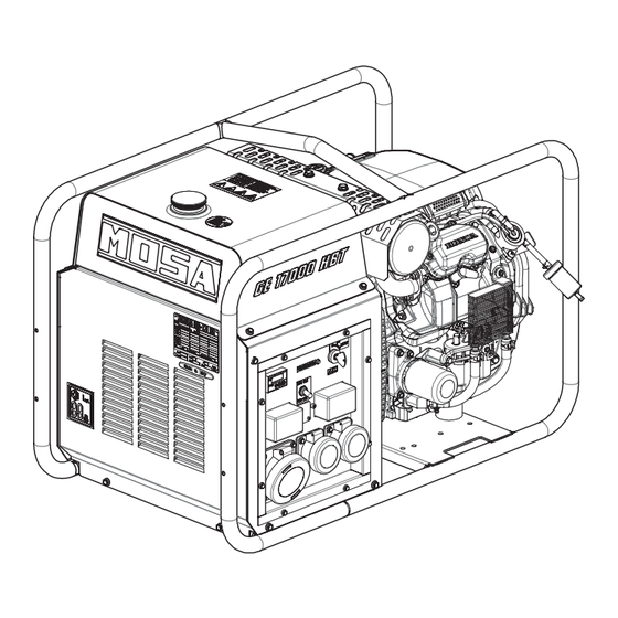
4. Description Description The Generating Set is a machine that transforms mechanical energy, generated by an engine, into electrical energy through an alternator. Main components 4.1.1 External components D5264680 Frame 11 - Oil filler plug Engine 12 - Muffler Central lifting point 13 - Engine air filter Fuel tank 14 - Engine air intake grid... -
Page 28: Control Panel And Electrical Panel Components (Mod. Ge 15000 Hbm)
4. Description 4.1.2 Control panel and electrical panel components (mod. GE 15000 HBM) D5264740 1 - Multi-purpose digital instrument: Volt - Hz / Total hour counter / - Partial hour counter (resettable) Auto-Idle switch (Auto-Ile versions) 3 - DIAGNOSTIC warning light - Oil alarm and engine malfunction Ignition and stop key Magnetic circuit breakers 5a - 2P 32A - C-curve for 32A 230V single-phase socket 5b - 2P 16A - C-curve for 16A 230V single-phase sockets (No. 2) -
Page 29: (Mod. Ge 17000 Hbt)
4. Description 4.1.3 Control panel and electrical panel components (mod. GE 17000 HBT) D5264450 1 - Multi-purpose digital instrument: Volt - Hz / Total hour counter / - Partial hour counter (resettable) Local - Remote Start switch (EAS version) 3 - DIAGNOSTIC warning light - Oil alarm and engine malfunction Ignition and stop key Main machine switch 2P 16A magnetic circuit breakers for 16A 230V sockets (No. 2) 16A 230V 2P+E CEE IP67 sockets 16A 230V 2P+E IP54 SCHUKO sockets (SCHUKO version) PE ground terminal EAS switchboard connector (EAS version) 10 - 32A 400V 3P+N+T CEE IP67 socket... -
Page 30: Control Panel And Electrical Panel Components (Mod. Ge 17054 Hbt)
4. Description 4.1.4 Control panel and electrical panel components (mod. GE 17054 HBT) D5264690 Hour counter Voltmeter Auto-Idle switch Ignition and stop key 5 - DIAGNOSTIC warning light - Oil alarm and engine malfunction Magnetic/residual current circuit breakers - 2P 16A - 30mA Type A for 16A 230V SHUCKO sockets (No. 2) 16A 230V 2P+T SCHUKO IP54 sockets Equipotential ground terminal... -
Page 31: Electrical Protection
4. Description Electrical protection 4.2.1 Main machine switch GE 1500 HBM GE 1700 HBT The generating set is protected against short circuits and overloads by a circuit breaker (1) located upstream of the system. Overload protection tripping is not instantaneous; it follows an overcurrent/time characteristic. The greater the overcur- rent, the shorter the tripping time. - Page 32 4. Description Alarm threshold adjustment Dip-switch Pre-alarm indication led Power supply presence indication led Alarm indication led Test button Reset button Pre-alarm threshold adjustment D5260390 SRI3/ D2 operation • ON indicator (4) indicates that the equipment is powered. • Pressing the test button (6) for at least 5 seconds, turns on the Alarm (5) and Pre-alarm (3) LEDs. •...
-
Page 33: Optional Equipment And Accessories
4. Description Optional equipment and accessories 4.3.1 Auto Idle Important • Run the engine for the time indicated in the table below before drawing power to supply loads. Ambient temperature Time required – -10°C 2 minutes -9°C – -5°C 1 minute ≤ -4°C 20 seconds The 'Auto Idle' function is used to reduce the number of... -
Page 34: Tcm6 Remote Control
4. Description 4.3.2 TCM6 remote control Important • The TMC6 remote control can only be connected on EAS generator sets. WARNING • Before starting the machine, carefully read section “2. Safety” and in particular paragraph “2.8 Precautions for generating sets with automatic or remote start-up”. Pairing the TCM6 remote control with the generating set allows it to be started and stopped remotely. -
Page 35: Eas Mains/Generator Switchboard
4. Description Note • In the REMOTE START position, the ignition key on the front panel is completely disabled. • Use the ignition key (4) of the TCM 6 remote control to start and stop the generator. 4.3.3 EAS mains/generator switchboard Important •... - Page 36 4. Description 3 - Set the Local-Remote Start switch (3) to the REMOTE STARTposition. LOCAL START REMOTE START D5264500 4 - Check that the EAS switchboard is in RESET mode; if not, press the RESET button (4). 5 - Perform the first start-up in MANUAL mode: a - Check that the main machine switch and other electrical protection switches are closed (switch lever up).
-
Page 37: Delivery And Unpacking
If this occurs, immediately inform the transport company and write down the "Conditional Acceptance” clause in the delivery note. • In the event that, at the time of delivery, significant damage is found, caused during transport, together with any missing parts that may be found, promptly notify MOSA Div. of BCS S.p.A. Unpacking • Unloading of the packaging must be carried out with the utmost care, using lifting equipment of a suitable capaci- ty (e.g. - Page 38 5. Delivery and unpacking 2 - Check the machine identification plate, the integrity of the decal and data, and read the use and maintenance manual before proceeding with use. D5264480...
-
Page 39: Installation
6. Installation Installation WARNING • Before proceeding with the installation, carefully read section Safety - “2.6 Precautions for positioning the machine” and “2.7 Precautions during operation”. • The installation and the electrical connection described in this chapter are indicative. For these operations, it is necessary to contact Specialized Technicians who must issue the necessary certifications. -
Page 40: Indoor Installation
6. Installation Indoor installation Important • The room where the generating set will be installed must comply with the legislation in force at the place of installation. Installation of the generating set indoor must be carried out in accordance with the instructions described. D5260270 Recommended minimum size Generating set... -
Page 41: Supporting Floor
6. Installation 6.3.1 Supporting floor For a correct support of the electronic unit and to avoid the transmission of vibrations, it is necessary to build a reinforced concrete platform (7) on the floor, isolated from the rest of the structure. The generating set frame must be fixed to the platform (7) with dowels or anchor bolts. The platform must have a length (D) and a width (E) greater than 400 mm (200 mm per side) with respect to the support base of the generating set (200 mm per side). -
Page 42: Grounding With Residual Current Circuit Breaker Or Earth Leakage Relay
6. Installation 6.4.3 Grounding with residual current circuit breaker or earth leakage relay Connection to a grounding system is mandatory for all models equipped with a residual current circuit break- er or earth leakage relay. In these groups, the star centre of the generating set is generally connected to the machine ground. By adopting the TN or TT distribution system, the differential relay guarantees protection against indirect contacts. -
Page 43: Operation
7. Operation Operation WARNING • Before starting the machine, carefully read section “2. Safety”. • It is forbidden to connect the set to the public grid and/or other source of electricity. Operating conditions 7.1.1 Power The electrical power of the generating set, expressed in kVA, is the available output power at the reference environmental conditions and at the rated values of: voltage, frequency, power factor (cos ϕ). -
Page 44: Checks Before Start-Up
7. Operation For cos ϕ values lower than 0.8, the alternator must be downgraded, because, at the same apparent power, the alternator should provide a greater reactive power. For the reduction coefficients, contact the Technical Support Service. Asynchronous motor start Starting an asynchronous motor by a generating set can be critical, due to the high starting currents that the asynchronous motor requires (Iavv. = up to 8 times rated current In.). The starting current must not exceed the overload current allowed by the alternator for short periods, gener- ally 250-300% for 10-15 seconds. -
Page 45: Starting The Generating Set
7. Operation Starting the generating set WARNING • Do not change the factory settings and do not tamper with sealed parts. 1 - Check that the main machine switch (1) is set to OFF (in- GE 1500 HBM GE 1700 HBT sertion lever downwards). - Page 46 7. Operation 5 - Turn the ignition key (4) to the ON position. 6 - Turn the ignition key (4) to the START. position 7 - When the engine starts, release ignition key. The key automatically returns to the ON position. Important START • The engine is equipped with an automatic choke (Auto Choke) that facilitates the starting phase and requires no manual operation on the choke (air) control.
-
Page 47: Stopping The Generating Set
7. Operation Stopping the generating set GE 1500 HBM GE 1700 HBT 1 - Turn off the loads connected to the generating set. 2 - Set the main machine switch (1) to OFF (insertion lever downwards). 3 - Allow the engine to run without load for a few minutes. GE 1754 HBT D5264520 4 - Turn the ignition key (4) to the “OFF” position. -
Page 48: Displaying Measurements And Resetting Working Hours With The Multi-Purpose Digital Instrument (Models Ge 15000 Hbm - Ge 17000 Hbt)
7. Operation Displaying measurements and resetting working hours with the multi-purpose digital instrument (models GE 15000 HBM - GE 17000 HBT) The multi-purpose digital instrument displays the following measurements: • U = Alternating voltage VAC • F = Frequency Hz • h = Total hour counter •... - Page 49 7. Operation To identify the fault or malfunction, please refer to the following table. Number of Fault/Failure Possible fault flashes Steady light Oil Alarm Faulty wiring or insufficient oil Battery voltage problem Faulty wiring or insufficient oil Regulator failure or excessive electrical Faulty accelerator load Faulty throttle opening sensor 1 Wiring fault or blocked throttle valve Faulty throttle opening sensor 2 Wiring fault or sensor failure...
- Page 50 7. Operation NOTES:...
-
Page 51: Maintenance
7. Maintenance Maintenance WARNING • Before proceeding with maintenance, carefully read section “2. Safety”. Refuelling Use fuel and lubricants according to the ambient temperature. 8.1.1 Fuel • Only use gasoline and fill the tank with clean fuel. • Keep the engine off during refuelling. • Fill the fuel tank up to the lower edge of the maximum level, and immediately dry any spilled fuel. 8.1.2 Engine oil •... -
Page 52: Checking And Cleaning The Engine Air Filter
7. Maintenance 8.1.3 Checking and cleaning the engine air filter Inspection 1 - Remove the air filter cover (1) and inspect the filter ele- ments (2) and (3). 2 - Clean any dirty filter elements and replace the damaged ones. D5264570 Cleaning 1 - Remove the air filter cover (1) 2 - Pull out the filter elements (2) and (3). 3 - Using a damp cloth, clean the inside of the cover (1) and the air filter box (4). -
Page 53: Routine Maintenance
7. Maintenance Routine maintenance WARNING • Pay the utmost attention to the generating sets equipped with an automatic or remote interven- tion system. Make sure that the generating set does not start during routine maintenance or repair opera- tions by carrying out the following operations: ◦... -
Page 54: Storage
7. Maintenance • Check engine oil, fuel, battery electrolyte levels. If necessary, top up with oil. • Check electric connections and clean control panel. Every year • Check electric connections and clean control panel. • Replace the engine oil. Storage •... - Page 56 MOSA div. della BCS S.p.A. Viale Europa, 59 20047 Cusago (Milano) Italy Tel.+39 - 0290352.1 Fax +39 - 0290390466 www.mosa.it...
Need help?
Do you have a question about the GE 15000 HBM and is the answer not in the manual?
Questions and answers