
Related Manuals for Mosa DP2500iL


Summary of Contents for Mosa DP2500iL
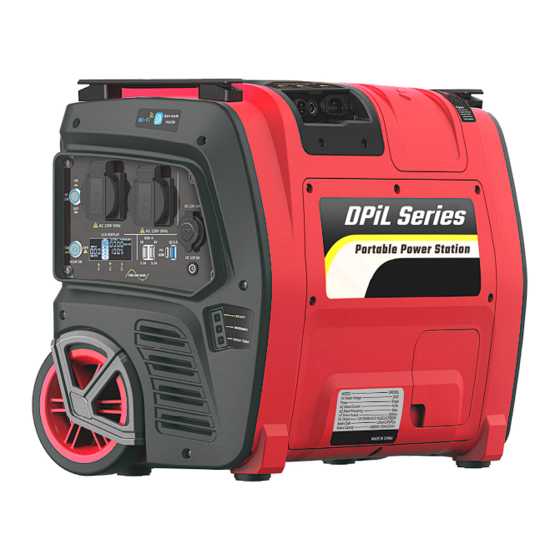
- Page 1 OWNER'S MANUAL PORTABLE POWER STATION DPiL Series DP1000iL / DP1500iL / DP2000iL / DP2500iL VER2.3-20220420...
-
Page 2: Table Of Contents
CONTENT 1. UNIT DESCRIPTION ................- 3 - 1.1 COMPONENTS IDENTIFICATION ..........- 3 - 1.2 OUTPUT PANEL ................- 4 - 1.3 CHARGING INPUT PANEL............. - 7 - 1.4 BATTERY CONNECTOR ..............- 8 - 2. - Page 3 INTRODUCTION Congratulations on your selection of a marvelous power station. This manual will provide you with a good basic understanding of the safe operation and maintenance of this machine, please read it carefully. Read this manual carefully before operating this power station. This manual should stay with this power station if it is sold.
-
Page 4: Unit Description
Please DO NOT modify the unit in any way, otherwise factory may reserve the right not to provide the complete warranty. 1. UNIT DESCRIPTION 1.1 COMPONENTS IDENTIFICATION (1). Output Panel: Location of power station controls and output receptacles. (2). Charging Input Panel: Location of power station charging input receptacles. -
Page 5: Output Panel
(6). Front Handle / Rear Handle: Two persons can carry the power station easily by these two handles. (7). Connector Cover: Open the cover to connect the Battery. Connector before charging or operating the power station. 1.2 OUTPUT PANEL ‐ 4 ‐ ... - Page 6 (1). AC Switch: This switch turns ON or OFF AC output of the power station. (2). AC Receptacle: AC output receptacles for connecting AC devices. (3). Main Switch: This switch turns ON or OFF DC output of the power station, and AC Switch is available only after the main switch is turned (4).
- Page 7 (8). 5.5mm Port: the 12V DC output receptacle for 5.5mm plugs. (9). 6mm Port: the 12V DC output receptacle for 6mm plugs. (10). LCD Display: Display remaining capacity of the battery, input/output watts, remaining operation hours or charging hours of the battery, battery voltage, total running time, and fault warnings.
-
Page 8: Charging Input Panel
1.3 CHARGING INPUT PANEL (1). PV Charging Input: Charge the power station from solar panels (optional equipment). (2). DC Charging Input: Charge the power station from cars. (3). AC Charging Input: Charge the power station from wall outlets or other AC power source. (4). -
Page 9: Battery Connector
1.4 BATTERY CONNECTOR You need to connect the battery connector 2 before charging or using the power station: (1). Open the connector cover 1. (2). Connect the battery connector 2 securely together with the connector 3 of the power station, otherwise the power station cannot be charged or used. -
Page 10: Pv Charging Input
The power station is fully charged when all battery segments in the LCD screen stop blinking and remain solid. 2.1 PV CHARGING INPUT Loosen ‐ 9 ‐ ... - Page 11 You can charge the power station from solar panels as follows: (1). Remove the cover 1 from PV charging port 2. (2). Connect PV charging port 2 to MC4 port 5 of solar panels 4 (optional equipment) by PV charging cable 3, which can be found in the packing box.
-
Page 12: Ac Charging Input
2.2 AC CHARGING INPUT You can charge the power station from wall outlets or other AC source as follows: Connect AC charging port 1 to wall outlets or other AC source by the AC charging cable 2, which can be found in the packing box. NOTE The voltage of the AC charging CAN NOT exceed the AC ... -
Page 13: Dc Charging Input
2.3 DC CHARGING INPUT You can charge the power station from cars as follows: Connect DC charging port 1 to cigarette lighter receptacle of 12V or 24V cars by DC charging cable 2, which can be found in the packing box. - Page 14 You can charge the power station from wind turbines as follows: (1). Remove the cover 1 from wind charging port 2. (2). Connect wind charging port 2 to wind charging cable 4 of wind turbines (optional equipment) by wind charging plug 3, which can be found in the packing box.
-
Page 15: Dc Quick Charging Input (Optional)
2.5 DC QUICK CHARGING INPUT (optional) Loosen You can charge the power station from DC 24V power unit as follows: (1). Unscrew the screw 1, and then open the cover 2. (2). Connect DC quick charging port 3 to DC quick charging cable 5 of DC 24V power unit (optional equipment) by DC quick charging plug 4, which can be found in the packing box. -
Page 16: Operating The Power Station
NOTE The voltage of the DC power unit CAN NOT exceed the DC QUICK INPUT voltage range. DO NOT short circuit the DC quick charging port 3! 3. OPERATING THE POWER STATION ‐ 15 ‐ ... -
Page 17: Dc Operation
3.1 DC OPERATION You can use the DC output from the power station as follows: (1). Push the main switch 3 to "ON" position. (2). Receptacle 4, 8 and 9 all are 12V DC output port, according to the plug type of 12V DC electric devices to choose suitable one to connect. (3). -
Page 18: Ac Operation
NOTE Be sure the receptacle load current is within receptacle rated current. If the DC output is overloaded (in excess of rated current), or if there is a short circuit in a connected appliance, the icon icon in LCD Display 10 will show(as shown in the figure below), and the DC output to the connected appliance(s) will shut off. - Page 19 AC output voltage is very high, operators must be protected from electric shock at all times. Do not operate with wet hand. Do not operate by children without supervision. Do not expose the power station to rain, moisture or snow. NOTE ...
-
Page 20: Lcd Display
If the AC output is overloaded (in excess of rated power), or if there is a short circuit in a connected appliance, the warning LED 15 will go ON, and the AC output to the connected appliance(s) will shut off. 4. - Page 21 INPUT shows the amount of power (watts) going into the battery while charging. If charging from solar, you will see the watts change as you reposition the panels into/out of the sunlight. OUTPUT shows the amount of power (watts) that your appliances are using while plugged into the power station.
- Page 22 POWER icon will show when the Gen-mate unit (optional equipment) inside the power station is operating normally. Wi-Fi icon will flash slowly when the power station equipped with Gen-mate unit (optional equipment) is connected to the Gen-mate APP in Smartphone by Wi-Fi. Fault code 032 means that DC output is overloaded or short-circuited.
-
Page 23: Connect The External Battery
5. CONNECT THE EXTERNAL BATTERY If the internal battery in the power station is empty, you can connect an external battery directly to increase the capacity without taking out the internal one: (1). -
Page 24: Replace The Battery
battery, and connect the battery connector 5 securely together with the connector 4 of the power station. NOTE Do not connect the battery connector 5 of the external battery to the battery connector 2 of the internal battery, otherwise the two batteries may be damaged. - Page 25 Screws Loosen Loosen Loosen ‐ 24 ‐ ...
-
Page 26: Install The Battery
(1). Loosen five screws and remove the maintenance cover 1. (2). Disconnect the battery connector 2. (3). Loosen the screws 5, 6 with a box spanner 3 to remove the battery baffle plate 4. The spanner 3 can be found in the packing box. (4). -
Page 27: Reinstall The Battery Into The Power Station
(3). Bind the bandage 1 around the battery 2. (4). Make sure the bandage 1 through the metal buckle 3 and pressed tightly by the metal buckle 3 as shown in the figure above. (5). The metal buckle 3 should be located on the left side as shown in the figure above. -
Page 28: Connect The Battery
be found in the packing box. (3). Make sure the metal buckle 6 has enough distance from the baffle plate 2 to avoid interfere. 6.2.3 CONNECT THE BATTERY Screws Tighten (1). Take out the battery connector 3 and the connector 4 of the power ‐ 27 ‐ ... -
Page 29: Transportation And Storage
station from the connector window 5 on the maintenance cover 1. (2). Insert the three bulge parts at the bottom of the maintenance cover 1 into the three installation holes at the bottom of the main case 2. Then put on the maintenance cover 1. (3). -
Page 30: Protection
station may overheat and damage the battery, or inverter. Store the unit in a clean, dry place. If possible, store the unit indoors and cover it to give protection from dust and dirt. 8. PROTECTION 8.1 INPUT PROTECTION Battery Charging Protection: When the battery is fully charged, the charging input will automatically shut down, and the all battery segments in the LCD screen will stop blinking and remain solid. - Page 31 reducing DC loads or eliminating short-circuited problems. Inverter Over Temperature Protection: When the temperature in the inverter is too higher, AC output will automatically shut down. The buzzer alarm will sound 5 times uninterruptedly and the warning light flashes 5 times at the same time. Turn off the electrical appliance connected to the power station, and put the power station in a cool place to cool it then reset the AC switch.
-
Page 32: Trouble Shooting
9. TROUBLE SHOOTING No DC Output Push the main switch to the Is the main switch OFF? ON position. Is the battery power too low? Charge the battery. Turn electrical Does the over temperature appliance connected to the indicator on the screen/panel or power station, and put the APP go on? power station in a cool place... - Page 33 Is there any fault on the DC Adjust replace electrical appliance? appliance. Contact with an authorized dealer. No AC Output Push the main switch to the Is the main switch OFF? ON position. Push the AC switch to the ON Is the AC switch OFF? ...
- Page 34 Is the AC output overloaded? Reduce loads and push the (The warning light on the panel AC switch to reset module. flashes) Check and correct condition of Is the AC electrical device short any extension cords and all circuit? (The warning light on items being powered, then the panel flashes) push the AC switch to reset...
-
Page 35: Specifications
10. SPECIFICATIONS DPiL SERIES SPECIFICATIONS Model DP1000iL DP1500iL DP2000iL DP2500iL Rated Power 1000VA 1500VA 2000VA 2500VA Peak Power 2000VA 3000VA 4000VA 5000VA Dimensions 530mm(20.9 in)X320mm(12.6 in)X430mm(16.9 in) Weight 34kg (75 lbs) 36kg (79 lbs) 41kg (90 lbs) Battery Type LiFePO... - Page 36 based on resistive load, and is not applicable to inductive load and capacitive load. Since the power factor of inductive load and capacitive load are less than 1, the rated power of inductive load and capacitive load shall be small enough compared with the rated power of the power station, and the ratio of the two shall not exceed the power factor of the load, otherwise the power station may be overloaded or damaged.
- Page 37 More power More smart EASY POWER WITH YOU...
Need help?
Do you have a question about the DP2500iL and is the answer not in the manual?
Questions and answers