Table of Contents
Advertisement
Quick Links
Advertisement
Table of Contents

Related Manuals for Keysight Technologies 34946A


Summary of Contents for Keysight Technologies 34946A
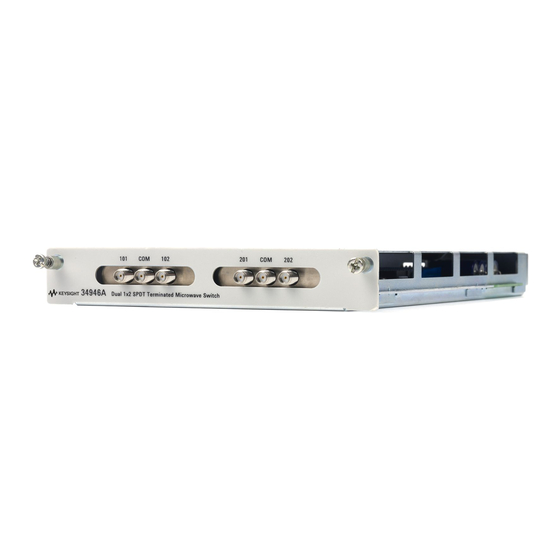
- Page 1 Keysight 34946A-34947A Microwave Switch/Driver Modules User’s Guide...
- Page 2 EXPRESS OR IMPLIED, WITH REGARD agreement and written consent from customarily provided to the public. TO THIS MANUAL AND ANY Keysight Technologies as governed by Accordingly, Keysight provides the INFORMATION CONTAINED HEREIN, United States and international Software to U.S. government INCLUDING BUT NOT LIMITED TO THE copyright laws.
-
Page 3: Safety Symbols
Caution, risk of electric shock Caution, risk of danger (refer to this Frame or chassis (ground) terminal manual for specific Warning or Caution information) Standby supply. Unit is not completely disconnected from ac mains when switch is off Keysight 34946A-34947A User’s Guide... -
Page 4: Additional Safety Notices
(grounding) conductor or disconnection of the protective earth terminal will cause a potential shock hazard that could result in personal injury. Do Not Operate in an Explosive Atmosphere Do not operate the instrument in the presence of flammable gases or fumes. Keysight 34946A-34947A User’s Guide... -
Page 5: Do Not Remove The Instrument Cover
In Case of Damage Instruments that appear damaged or defective should be made inoperative and secured against unintended operation until they can be repaired by qualified service personnel. Keysight 34946A-34947A User’s Guide... -
Page 6: Waste Electrical And Electronic Equipment (Weee) Directive 2002/96/ Ec
To contact Keysight for sales and technical support, refer to the support links on the following Keysight websites: – www.keysight.com/find/34980a (product-specific information and support, software and documentation updates) – www.keysight.com/find/assist (worldwide contact information for repair and service) Keysight 34946A-34947A User’s Guide... -
Page 7: Table Of Contents
........6 34946A and 34947A Dual/Triple Microwave Switch Modules . - Page 8 THIS PAGE HAS BEEN INTENTIONALLY LEFT BLANK. Keysight 34946A-34947A User’s Guide...
- Page 9 List of Figures Figure 1-1 34946A and 34947A Option 001 Installation..14 Figure 1-2 N1810/11/12 Switch and D-Sub Connector Pinouts. Figure 1-3 34946A Simplified Schematic....17 Figure 1-4 34947A Simplified Schematic.
- Page 10 THIS PAGE HAS BEEN INTENTIONALLY LEFT BLANK. Keysight 34946A-34947A User’s Guide...
-
Page 11: 34946A And 34947A Dual/Triple Microwave Switch Modules
Switch reference document number: 5968-9653E 34946A Option 001 contains cables and connectors to support two of the supported switches listed above. 34947A Option 001 contains cables and connectors to support three Keysight N1810UL switches. The 34946A and 34947A modules do not connect to the analog buses. Instead, all connections are made through the visible SMA connectors via external cables. - Page 12 Micro-Coax http://www.micro-coax.com S. M. Electronics L.L.C. http://www.smelectronics.us The 34946A and 34947A support only 24 VDC coil options for the N1810 CAUTION switches. If the proper voltage option (Opt. 124) is not used, the switches could be damaged. The 34946A module (Options 004, 020, 026) has two independent Keysight N1810TL switches.
-
Page 13: 34946A And 34947A Option 001 Installation
The steps for installing the cable assembly and 9-pin D-Sub connectors are as follows: 1 Remove the 34946A or 34947A cover by removing the screw (T-10 torx) on the top of the instrument (Figure 1). Use care when handling the 34946A or 34947A chassis with the cover... - Page 14 Figure 1-1 34946A and 34947A Option 001 Installation. 4 Insert the ribbon cable strand into the D-Sub connector as shown. Align the metal contacts of the connector over the pins. Press the connector onto the strand using a vise or clamp to press the contacts evenly through the cable insulation.
-
Page 15: 34946A And 34947A Scpi Programming Examples
8 6 4 2 Figure 1-2 N1810/11/12 Switch and D-Sub Connector Pinouts. 34946A and 34947A SCPI Programming Examples The programming examples below provide you with SCPI command examples to use for actions specific to the microwave switch modules. The slot and channel addressing scheme used in these examples follow the form sccc where s is the mainframe slot number (1 through 8) and ccc is the three-digit channel number. -
Page 16: Installing Sma Connectors
When installing SMA connectors, it is recommend that you tighten them to 0.8 - 1.1 Nm (7-10 in-lbs) of torque. 34946A and 34947A Simplified Schematics Figures 3 and 4 show the channel configurations for the 34946A and 34947A modules, respectively. Keysight 34946A-34947A User’s Guide... - Page 17 Figure 1-3 34946A Simplified Schematic. Figure 1-4 34947A Simplified Schematic. Keysight 34946A-34947A User’s Guide...
- Page 18 THIS PAGE HAS BEEN INTENTIONALLY LEFT BLANK. Keysight 34946A-34947A User’s Guide...
- Page 19 Option 001 installation programming examples simplified schematic verification 34947A Option 001 installation programming examples simplified schematic verification connectors N1810TL switches N1810UL switches Option 001 34946A 34947A programming examples safety notices SMA connectors switch verification verification 34946A 34947A Keysight 34946A-34947A User’s Guide...
- Page 20 THIS PAGE HAS BEEN INTENTIONALLY LEFT BLANK. Keysight 34946A-34947A User’s Guide...
- Page 21 This information is subject to change without notice. Always refer to the Keysight website for the latest revision. © Keysight Technologies 2008-2019 Edition 4, July 1, 2019 Printed in Malaysia *34980-90046* 34980-90046 www.keysight.com...
Need help?
Do you have a question about the 34946A and is the answer not in the manual?
Questions and answers