
Related Manuals for Eneo NXP-880F21


Summary of Contents for Eneo NXP-880F21
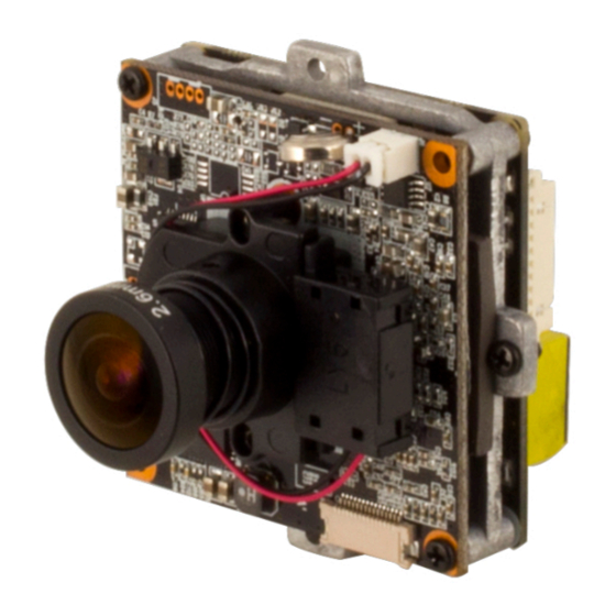
- Page 1 User Manual 1/2.8” Network Board Camera, 1920x1080, Day&Night, D-WDR, PoE, 12V NXP-880F26 NXP-880F21...
- Page 2 WARNING TO REDUCE THE RISK OF FIRE OR ELECTRIC SHOCK, DO NOT EX- POSE THIS PRODUCT TO RAIN OR MOISTURE. DO NOT INSERT ANY METALLIC OBJECT THROUGH THE VENTILATION GRILLS OR OTHER OPENNINGS ON THE EQUIPMENT. CAUTION CAUTION RISK OF ELECTRIC SHOCK DO NOT OPEN WARNING: TO REDUCE THE RISK OF ELECTRIC SHOCK, DO NOT REMOVE COVER (OR BACK).
- Page 3 FCC COMPLIANCE STATEMENT This device complies with Part 15 of the FCC Rules. Operation is subject to the following two conditions: (1) this device may not cause harmful inter- ference, and (2) this device must accept any interference received, including interference that may cause undesired operation.
- Page 4 IMPORTANT SAFETY INSTRUCTIONS 1. Read these instructions. 2. Keep these instructions. 3. Heed all warnings. 4. Follow all instructions. 5. Do not use this apparatus near water. 6. Clean only with dry cloth. 7. Do not block any ventilation openings. Install in accordance with the manufacturers in- structions.
-
Page 5: Table Of Contents
Contents 1 Network Connection & IP assignment 2 Operation 2.1 Access from a browser ......2.2 Access from the internet . -
Page 6: Network Connection & Ip Assignment
CD with a simple double click to use the program After pushing the button „Find eneo devices“ you will get a list of cameras connected to the local network. Highlight your camera in the list and open a context menu with a click of the right mouse button. -
Page 7: Operation
2 Operation The network camera can be used with Windows operating system and browsers. The rec- ommended browsers are Internet Explorer, Safari, Firefox, Opera and Google Chrome with Windows. NOTE: To view streaming video in Microsoft Internet Explorer, set your browser to allow ActiveX controls. -
Page 8: Access From The Internet
2.2 Access from the internet Once connected, the network camera is accessible on your local network (LAN). To access the network camera from the Internet you must configure your broadband router to allow incoming data traffic to the network camera. To do this, enable the NAT traversal feature, which will attempt to automatically configure the router to allow access to the network cam- era. -
Page 9: Live View Page
2.4 Live View Page The Live View page comes in several screen modes: 1920x1080, 1280x1024, 1280x720(960), 1024x768, 704x480(576), 640x480(360) and 320x240. Users are allowed to select the most suitable one out of those modes. Adjust the mode in accordance with your PC specifications and monitoring purposes. - Page 10 2) Control toolbar The live viewer toolbar is available in the web browser page only. It displays the following buttons: The Stop button stops the video stream being played. Pressing the key again toggles the start and stop. The Start button connects to the network camera or starts playing a video stream.
- Page 11 The Mic button activates/deactivates microphone input. Use this scale to control the volume of the speakers and microphones. 3) Video Streams The network camera provides several images and video stream formats. Your require- ments and the properties of your network will determine the type you use. The Live View page in the network camera provides access to H.264 and Motion JPEG video streams, and to the list of available video streams.
-
Page 12: Playback
2.5 Playback The Playback window contains a list of recordings made to the memory card. It shows each recording’s start time, length, the event type used to start the recording, calendar and time slice bar indicates if the recording is existed or not. The description of playback window follows. - Page 13 (3) Time Chart Display an hour-based search screen for the chosen date. If there is recording data, a blue section will be displayed on a 24-hour basis. If you select a particular hour in the chart, a yellow square on the hour will be displayed. (4) Speaker Control Bar Use this scale to control the volume of the speakers.
-
Page 14: Network Camera Setup
2.6 Network Camera Setup This section describes how to configure the network camera. Administrator has unrestricted access to all the Setup tools, whereas Operators have access to the settings of Basic Configuration, which are Live View, Video & Image, Audio, Event, Dome Configuration, and System. - Page 15 1) Users User access control is enabled by default. The administrator can set up other users, by giving user names and passwords. It is also possible to allow anonymous viewer login, which means that anybody may access the Live View page, as described below: The user list displays the authorized users and user groups (levels): User Group Authority...
- Page 16 2) Network The network camera supports both IP version 4 and IP version 6. Both versions may be enabled simultaneously, and at least one version must always be enabled. When using IPv4, the IP address for the network camera can be set automatically via DHCP, or a static IP address can be set manually.
- Page 17 3) Video & Image User can setup and change setting of individual video stream in this page. Please refer to “Video & Image > Basic” for more details about Video & Image setup. 4) Audio The network camera can transmit audio to other clients using an external microphone and can play audio received from other clients by attaching a speaker.
-
Page 18: Live View
5) Date & Time User can set time directly or assign time server to get the current time, as well as determine Date & Time format in this page. Please refer to “System > Date & Time” for more details about Date & Time setup. 2.6.2 Live View •... -
Page 19: Video & Image
2.6.3 Video & Image 1) Basic • Stream 1 Setting: – Codec: The codec supported in Stream 1 is H.264. There are 3 pre-programmed stream profiles available for quick set-up. Choose the form of video encoding you wish to use from the drop-down list: ·... - Page 20 704x576, 704x480, 640x480, 640x360 and 320x240. Users can change the se- lected screen size anytime while monitoring the screen on a real-time basis. – Bitrate control: The bit rate can be set as Variable Bit Rate (VBR) or Constrained Variable Bit Rate (CVBR).
- Page 21 2) Privacy Masking The privacy masking function allows you to mask parts of the video image to be transmitted. You can set up to eight privacy masks. You can choose masking type among Black, Mosaic, and Black Mosaic. Black mosaic is a mosaic with added black. The masking type applies to all Mask windows.
- Page 22 3) Webcasting The live video of the camera can be streamed to a website. User can copy and paste the HTML code generated on the screen to the website page code, where user wants to display live video. NOTE: To use webcasting service, the Enable Anonymous viewer login option must be checked.
- Page 23 4) Camera Setup In this page, user can setup Exposure Control, White Balance Control, Image Appearance, Day&Night control, and IR Control. • Video Preview: User can check the setting via video preview pop-up window...
- Page 24 • Exposure Control 1. Mode: Determines exposure mode among automatic and flicker-free modes. 2. Value: Sets exposure value between 1 and 10 using slidebar or manual type in. 3. Max. gain: Sets maximum gain threshold. 4. Shutter: Determines shutter mode between automatic and fixed. For automatic 6 sets the maximum shutter speed, and for fixed 5 sets the shutter speed for the camera.
- Page 25 • Image Appearance This provides access to the advanced image settings for the network camera. – Brightness: The image brightness can be adjusted in the range 1-10, where a higher value produces a brighter image. – Contrast: Adjust the image’s contrast by raising or lowering the value in this field. –...
- Page 26 • Day & Night Control User can setup Day & Night operation mode among Automatic, Day, and Night. – Mode: · Automatic: Normally displays color image, and switches automatically to black & white image after the ambient light level reaches a pre-defined thresh- old.
- Page 27 5) OSD This camera provides two OSD’s (on screen display) on each stream, title and date & time. User can drag green “OSD Title” and “Date & Time” to the desired position and check at preview window. • Video Preview: User can check the position of OSD on actual video via preview pop- up window.
-
Page 28: Audio
2.6.4 Audio The network camera can transmit audio to other clients using an external microphone and can play audio received from other clients by attaching a speaker. The Setup page has an additional menu item called Audio, which allows different audio configurations, such as full duplex and simplex. - Page 29 – Output volume: If the sound from the speaker is too low or high it is possible to adjust the output gain for the active speaker attached to the network camera. – Mute: User can disable the output audio transmission by checking the box. When the settings are complete, click Save button to save the settings, or click Reset button to clear all of the information you entered without saving it.
-
Page 30: Event
2.6.5 Event 1) Event In ∇ On Boot This is used to trigger an event every time the network camera is started. Select “Enable on boot” to activate the On Boot event. Enter the Dwell time the event lasts from the point of detection, 1-180 seconds. When the settings are complete, click Save button to save the settings, or click Reset button to clear all of the information you entered without saving it. - Page 31 ∇ Alarm In This camera provides 1 Alarm In port and user can set the port. The Port can be given as Normally Open or Normally Close state, and its Normal state can be configured. In order to use the alarm port, check the “Enable alarm port 1” first. •...
- Page 32 ∇ Manual Trigger This option makes use of the manual trigger button provided on the Live View page, which is used to start or stop the event type manually. Alternatively, the event can be triggered via the product’s API (Application Programming Interface). Select “Enable manual trigger”...
- Page 33 ∇ Motion This option makes use of the motion detection function with 16 programmable areas, 8 Include and Exclude zones each. Click right mouse button on the preview window shows selection pop-up of New Motion, New Mask, Select, Delete, and Freeze. Select New Motion and click&drag generates an Include box of green color.
- Page 34 – Dwell time: Determines how long the triggered event holds from the last trigger- ing. – Show Histogram: This camera provides live histogram for easy setup of thresh- old level in motion window. The pop-up window shows activity strength and threshold level, and user can determine threshold level for triggering motion event by slide bar or type in number.
- Page 35 ∇ Network Loss This is used to trigger an event every time the network connection is failed. Select “Enable network loss” to activate the Network Loss event. Select a dwell time for how long the event will last from the point of detection. When the settings are complete, click Save button to save the settings, or click Reset button to clear all of the information you entered without saving it.
- Page 36 ∇ Tampering This is used to trigger an event when camera tampering occurs, for example, obstruct the camera with foreign material or move camera direction using external force. Select “Enable tampering” to activate the Tampering event. • Dwell time: Determine how long the event will last from the point of detection. When the settings are complete, click Save button to save the settings, or click Reset button to clear all of the information you entered without saving it.
- Page 37 ∇ VCA The network cameras provide VCA(Video Content Analysis) functions of “Line Detector” and “Field Detector.” • Video Content Analysis Setting Check Enable video content analysis box to use a VCA function. – Object: Determines detection sensitivity. · Sensitivity: As the value becomes bigger, the detection sensitivity increases. ·...
- Page 38 – Detection Rule: User can assign up to 3 different rules for each preset position. · Line Detector Once selected, a red line appears on the video preview window. Drag and drop the line at the desired position. User can change the length and the slope by dragging each end of the line.
- Page 39 ∇ AIHM AIHM(Advanced Intelligent Health Monitoring) triggers an event when abnormality of the camera occurs. Select “Enable AIHM” to activate the AIHM function. • Enable record status check: Trigger event if the record status is modified. • Enable format event: Trigger event if the micro-SD card is formatted. When the settings are complete, click Save button to save the settings, or click Reset button to clear all of the information you entered without saving it.
- Page 40 ∇ Time Trigger Time Trigger is to set alarms at specific time. User can set up to four time triggers and each time trigger can be set to specific date in the calendar, every day, day of the week, or date of every month.
- Page 41 2) Event Out ∇ SMTP(E-Mail) The network camera can be configured to send event and error email messages via SMTP (Simple Mail Transfer Protocol). • SMTP (E-Mail) Setting: Select “Enable” to activate the SMTP operation. – Sender: Enter an email address to be used as the sender for all messages sent by the network camera.
- Page 42 • SMTP (E-Mail) Test: User can check the SMTP setting via a sample email. – Receiver: Enter an email address and click the Test button to test that the mail servers are functioning and that the email address is valid. When the settings are complete, click Save button to save the settings, or click Reset button to clear all of the information you entered without saving it.
- Page 43 ∇ FTP & JPEG When the network camera detects an event, it can record and save images to an FTP server. Images can be sent as e-mail attachments. Check the “Enable FTP” box to enable the service. This camera can support multiple FTP servers and user can configure each server settings separately.
- Page 44 – Post-event: This function is the counterpart to the pre-trigger buffer described above and contains images from the time immediately after the trigger. Configure as for pre-event. – Prefix file name: This name will be used for all the image files saved. If suffixes are also used, the file name will take the form <prefix>...
- Page 45 ∇ Alarm Out When the network camera detects an event, it can control external equipment connected to its alarm output port. • Enable alarm out: If selected, the output becomes activated for as long as the event is active. • Type: Select a type of NO (Normally Open) or NC (Normally Closed). When the settings are complete, click Save button to save the settings, or click Reset button to clear all of the information you entered without saving it.
- Page 46 ∇ Audio Alert When the network camera detects an event, it can output a predefined audio data to external speaker. Check the “Enable audio alert” box to enable the service. • Audio Alert Setting To use the audio alert with the network camera, an audio data file made by user must be uploaded from your PC.
- Page 47 ∇ Record When the network camera detects an event, it can record the video stream onto the Micro SD Memory (not supplied) or NAS (Network Attached Device) as a storage device. Check the “Enable Record” box to enable the service. •...
- Page 48 – SD: Mounted SD card. – CIFS: A file format for a NAS device. – NFS: A file format for a NAS device. NOTE 1: Common Internet File System (CIFS) is a remote file access protocol that forms the basis for Windows file sharing, network printing, and various other network services.
- Page 49 ∇ XML Notification When the network camera detects an event, Notification server is used to receive notification messages as a type of XML data format. Check the box to enable the service. • XML Notification Setting: – Notification server URL: The network address to the server and the script that will handle the request.
- Page 50 ∇ Boost The Boost feature is used in conjunction with event detection. When this feature is turned ON, the Frame rate and Bit rate in the boost condition can be set to a different value than the ones in the normal condition field. When an event is detected, the camera will boost the Frame rate and Bit rate from the normal condition to this boosted level for the duration of the event.
- Page 51 ∇ Notification Server When the network camera detects an event, the Notification Server is used to receive up- loaded image files and/or notification messages. Check the box to enable the service. • Notification Server Setting: – Type: User can select message transmission type among HTTP, HTTPS, TCP, and UTP.
- Page 52 3) Event Map The event map allows you to change the settings and establish a schedule for each event trigger from the network camera; up to a max. 15 events can be registered. Click the Add button to make a new event map; a popup window displays as below. To change an existing event, select that event and click the Modify button;...
- Page 53 • General: Enter the name for a new event map. • Event In: Select an event type in the drop-down list. • Event Out: – E-mail: Select the email addresses you want to notify via email that an event has occurred.
-
Page 54: System
2.6.6 System 1) Information You can enter the system information. This page is very useful when you require device information after installation. • Device Name Configuration: Enter the device name. • Location Configuration: Enter the location information. You can enter up to four locations. - Page 55 2) Security ∇ Users User access control is enabled by default when the administrator sets the root password on first access. New users are authorized with user names and passwords, or the administrator can choose to allow anonymous viewer login to the Live View page, as described below: •...
- Page 56 ∇ HTTPS For greater security, the network camera can be configured to use HTTPS (Hypertext Trans- fer Protocol over SSL (Secure Socket Layer)). Then all communication that would otherwise go via HTTP will instead go via an encrypted HTTPS connection. •...
- Page 57 ∇ IP Filtering Checking the Enable IP address filtering box enables the IP address filtering function. Up to 256 IP address entries may be specified (a single entry can contain multiple IP ad- dresses). Click the Add button to add new filtered addresses. When the IP address filter is enabled, addresses added to the list are set as allowed or de- nied addresses.
- Page 58 ∇ OpenVPN OpenVPN is a Virtual Private Network using OpenSSL authentication. User can set the camera in either Server mode or Client mode. • OpenVPN Server Mode 1. Select Enable openVPN activates mode selection buttons. Choose Server mode, then Server Mode Configuration appears where you can configure Server Mode Settings.
- Page 59 • OpenVPN Client Mode 1. Select Enable openVPN activates mode selection buttons. Choose Client mode, then Client Mode Configuration appears where you can configure Client Mode Settings. 2. In Client Mode Configuration, you can setup Server URL, Protocol type, Port num- ber, LZO usage, and Renegotiation time.
- Page 60 3) Date & Time • Current Server Time This displays the current date and time (24h clock). The time can be displayed in 12h clock format (see below). • New Server Time – Time zone Select your time zone from the drop-down list. If you want the server clock to automatically adjust for daylight savings time, check the box “Automatically adjust for daylight saving time changes”.
- Page 61 4) Network ∇ Basic • IP Address Configuration: – Obtain IP address via DHCP: Dynamic Host Configuration Protocol (DHCP) is a protocol that lets network administrators centrally manage and automate the assignment of IP addresses on a network. DHCP is enabled by default. Although a DHCP server is mostly used to set an IP address dynamically, it is also possible to use it to set a static, known IP address for a particular MAC address.
- Page 62 – Obtain DNS Server via DHCP: Automatically use the DNS server settings pro- vided by the DHCP server. – Use the following DNS server address to enter the desired DNS server by spec- ifying the following: · Domain name: Enter the domain(s) to search for the host name used by the network camera.
- Page 63 ∇ DDNS • Internet DDNS (Dynamic Domain Name Service) When using the high-speed Internet with the telephone or cable network, users can operate the network camera on the floating IP environment in which IPs are changed at every access. Users should receive an account and password by visiting a DDNS service like http://www.dyndns.com/.
- Page 64 ∇ RTP Create a setting for sending and receiving an audio or video on a real-time basis. These settings are the IP address, port number, and Time-To-Live value (TTL) to use for the media stream(s) in multicast H.264 format. Only certain IP addresses and port numbers should be used for multicast streams.
- Page 65 ∇ UPnP The network camera includes support for UPnP. UPnP is enabled by default, so the network camera is automatically detected by operating systems and clients that support this protocol. Enter a name in the Friendly name field. NOTE: UPnP must be installed on your workstation if running Windows XP. To do this, open the Control Panel from the Start Menu and select Add/Remove Programs.
- Page 66 ∇ QoS Quality of Service (QoS) provides the means to guarantee a certain level of a specified re- source to selected traffic on a network. Quality can be defined as a maintained level of bandwidth, low latency, and no packet losses. The main benefits of a QoS-aware network are: 1.
- Page 67 – Automatic frame rate: Selected if not influenced by a network-related program or equipment without a limitation on the network bandwidth. When the settings are complete, click Save button to save the settings, or click Reset button to clear all of the information you entered without saving it.
- Page 68 ∇ NAT (Port Mapping) • NAT Settings – Enable: Check this box to enable NAT traversal. When enabled, the network camera attempts to configure port mapping in a NAT router on your network, using UPnP. Note that UPnP must be enabled in the network camera (see System > Network >...
- Page 69 ∇ Zeroconf Zero configuration networking (zeroconf) is a set of techniques that automatically creates a usable Internet Protocol (IP) network without manual operator intervention or special config- uration servers. Zero configuration networking allows devices such as computers and printers to connect to a network automatically.
- Page 70 ∇ Bonjour The network camera includes support for Bonjour. When enabled, the network camera is automatically detected by operating systems and clients that support this protocol. Click the check box to enable Bonjour. Enter a name in the Friendly name field. NOTE: Also known as zero-configuration networking, Bonjour enables devices to automat- ically discover each other on a network, without having to enter IP addresses or configure DNS servers.
- Page 71 5) Language Select a user language. The language choices are English, Korean, French, German, Rus- sian and Chinese. When the settings are complete, click Save button to save the settings, or click Reset button to clear all of the information you entered without saving it.
- Page 72 6) Maintenance • Maintenance: – Restart: The unit is restarted without changing any of the settings. Use this method if the unit is not behaving as expected. – Reset: The unit is restarted and most current settings are reset to factory default values.
- Page 73 7) Support The support page provides valuable information on troubleshooting and contact information, should you require technical assistance. • Logs: The network camera supports system and event log information. Click the Sys- tem Log button to get the system log data or the Event Log button to get information on events.
- Page 74 – Networks Check: Click the Network Check button to get the information about the cameras network setting and traffic. You can see the pop-up window below. – Hardware Check: Click the Hardware Check button to diagnose the cameras hardware like video.
-
Page 75: Help
Help The Help information window will be provided as a popup window so that users can open and read it without needing to log-in. It will offer a description of the setting and Help page so that users can manipulate the network camera without a reference to the manual. -
Page 76: A Appendix
A Appendix A.1 Troubleshooting Troubleshooting if problems occur, verify the installation of the network camera with the instructions in this manual and with other operating equipment. Isolate the problem to the specific piece of equipment in the system and refer to the equipment manual for further information. -
Page 77: Alarm Connection
A.2 Alarm Connection The following connection diagram gives an example of how to connect a network camera. A.3 Preventive Maintenance Preventive maintenance allows detection and correction of minor that faults before they be- come serious and cause equipment failure. Every three-month, perform the following maintenance. 1. -
Page 78: System Requirement For Web Browser
A.4 System Requirement for Web Browser • Operating System: Microsoft Windows OS Series • CPU: Intel Core 2 Duo 2GHz or higher, 1GB RAM or more, 10GB free disk or higher • VGA: AGP, Video RAM 32MB or higher (1024x768, 24bpp or higher) A.5 General Performance Considerations When setting up your system, it is important to consider how various settings and situations will affect performance. - Page 79 Videor E. Hartig GmbH Exclusive distribution through special- ised trade channels only. Videor E. Hartig GmbH Carl-Zeiss-Straße 8 63322 Rödermark/Germany Tel. +49 (0) 6074 / 888-0 Technical changes reserved Fax +49 (0) 6074 / 888-100 www.videor.com...
Need help?
Do you have a question about the NXP-880F21 and is the answer not in the manual?
Questions and answers