Table of Contents
Advertisement
Quick Links
Advertisement
Table of Contents

Related Manuals for Eneo NXD Series


Summary of Contents for Eneo NXD Series
- Page 1 INSTALLATION / OPERATION / USER’S MANUAL NXD Series MEGAPIXEL NETWORK CAMERA...
-
Page 2: Warnings And Cautions
WARNINGS AND CAUTIONS: TO REDUCE THE RISK OF FIRE OR ELECTRIC SHOCK, DO NOT EXPOSE THIS PRODUCT TO RAIN OR MOISTURE. DO NOT INSERT ANY METALLIC OBJECTS THROUGH THE VENTILATION GRILLS OR OTHER OPENINGS ON THE EQUIPMENT. CAUTION CAUTION RISK OF ELECTRNIC SHOCK DO NOT OPEN CAUTION: TO REDUCE THE RISK OF ELECTRIC SHOCK, DO NOT REMOVE COVER (OR BACK). -
Page 3: Fcc Compliance Statement
FCC COMPLIANCE STATEMENT FCC INFORMATION: THIS EQUIPMENT HAS BEEN TESTED AND FOUND TO COMPLY WITH THE LIMITS FOR A CLASS A DIGITAL DEVICE, PURSUANT TO PART 15 OF THE FCC RULES. THESE LIMITS ARE DESIGNED TO PROVIDE REASONABLE PROTECTION AGAINST HARMFUL INTERFERENCE WHEN THE EQUIPMENT IS OPERATED IN A COMMERCIAL ENVIRONMENT. -
Page 4: Important Safeguards
IMPORTANT SAFEGUARDS 1. READ INSTRUCTIONS -- All the safety and operating instructions should be read before the appliance is operated. 2. RETAIN INSTRUCTIONS -- The safety and operating instructions should be retained for future reference. 3. CLEANING -- Unplug video monitor or equipment from the wall outlet before cleaning. Do not use liquid cleaners or aerosol cleaners. - Page 5 10. POWER CORDS -- Do not allow anything to rest on the power cord. Do not locate video monitor or equipment where the cord will be abused by persons walking on it. 11. HEED WARNINGS -- Follow all instructions marked on the video monitor or equipment. 12.
-
Page 6: Table Of Contents
CONTENTS DESCRIPTION ----------------------------------------------------------------------------------------------------10 Key Features --------------------------------------------------------------------------------------------10 Components --------------------------------------------------------------------------------------------11 Camera Layout -----------------------------------------------------------------------------------------12 INSTALLATION ---------------------------------------------------------------------------------------------------14 Before Installation -------------------------------------------------------------------------------------14 Starting Installation ------------------------------------------------------------------------------------14 Base Installation --------------------------------------------------------------------------------------14 Heater Kit Installation (Optional) --------------------------------------------------------------------16 Heater Power Consumption --------------------------------------------------------------------------16 Micro SD card Installation (Optional) ---------------------------------------------------------------16 OPERATION -------------------------------------------------------------------------------------------------------17 Minimum conditions for using web browser -------------------------------------------------------17 Accessing the IP camera ------------------------------------------------------------------------------17 Main Menu ----------------------------------------------------------------------------------------------18 LIVE VIEW --------------------------------------------------------------------------------------------------------18... - Page 7 Event Out – Audio Alert -------------------------------------------------------------------------------66 Event Out – Audio Alert – Audio Recorder -------------------------------------------------------67 Event Out – SD Record--------------------------------------------------------------------------------69 Event Map -----------------------------------------------------------------------------------------------70 Event Map – Add ---------------------------------------------------------------------------------------71 SD Playback – SD Playback List View ---------------------------------------------------------------73 Security – Users ----------------------------------------------------------------------------------------75 Security –...
- Page 8 LIST of ILLUSTRATIONS Figure 1. Mounting Hole ----------------------------------------------------------------------------------------14 Figure 2. Lock Screw --------------------------------------------------------------------------------------------15 Figure 3. Mount electric box ------------------------------------------------------------------------------------15 Figure 4. Heater Kit Installation --------------------------------------------------------------------------------16 Figure 5. Heater Power Consumption -------------------------------------------------------------------------16 Figure 6. Main Live View Page ---------------------------------------------------------------------------------19 Figure 7. Basic Configuration -----------------------------------------------------------------------------------21 Figure 8.
- Page 9 Figure 45. System / Security – Users / Add User -----------------------------------------------------------76 Figure 46. System / Security – Users / Modify User --------------------------------------------------------77 Figure 47. System / Security – HTTPS ------------------------------------------------------------------------78 Figure 48. System / Security – IP Filtering -------------------------------------------------------------------80 Figure 49. System / Date & Time ------------------------------------------------------------------------------81 Figure 50.
-
Page 10: Description
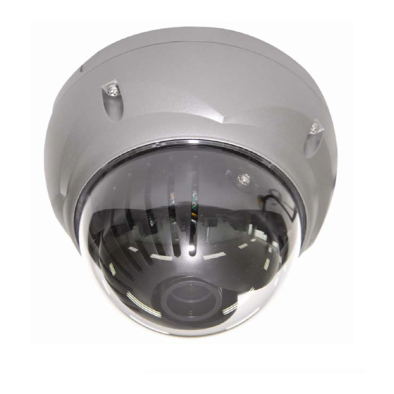
DESCRIPTION ------------------------------------------------------------------------------------------------------------------------------------- The NXD Series camera is an internet protocol based megapixel network camera with a built-in web based viewer on Internet Explorer®. The camera has a connection feature for third-party applications and compatible with supplied Utility software for easy installation and Client software to search, configure, manage, live view, record and playback. -
Page 11: Components
- Voice Alert Linked to Alarm Detection The NXD Series can play the audio file stored in the camera in synchronization with alarm detection by the sensor input or the motion detection function. -
Page 12: Camera Layout
Camera Layout Top View Lens: Allows wide area to be monitored Connection Cable: 26pin camera extension cable Connection Cable Main POWER connection - RED; DC12V or AC24V - WHITE; GND or AC24V Heater POWER connection (Optional) - ORANGE; DC12V or AC24V - BLACK;... - Page 13 - GREEN; GND - YELLOW; Alarm Input 2 - BROWN; GND - Light BLUE; Alarm Out - GRAY; GND RJ-45 connection: Connect Ethernet cable or supplies power to the camera if PoE is available. BNC connection: Connect BNC cable for composite video output. SPEAKER connection (GRAY): Connect external speaker for audio output.
-
Page 14: Installation
INSTALLATION ------------------------------------------------------------------------------------------------------------------------------------- Before Installation Before installing the camera, thoroughly familiarize yourself with the information in this section of the manual. - Recommends connecting the camera to a network that use a DHCP (Dynamic Host Configuration Protocol) server to address devices. - To ensure secure access to the IP camera, place the camera behind a firewall when it is connected to a network. -
Page 15: Figure 2. Lock Screw
4. Unlock torx screws (4x) the dome cover and fix the dome case firmly with supplied mounting screws (4x), plastic anchors (4x), O-Rings (4x). 5. Adjust desired focus and scene by turning and moving the hemisphere by hand. 6. Lock the housing cover with torx screws (4x). Figure 2. -
Page 16: Heater Kit Installation (Optional)
Heater Kit Installation (Optional) 1. Place the heater element is slot “A”. Please ensure that the cables are facing upwards and the heater is pointing towards the Dome. 2. Place the PCB in slot “B”. Please ensure that the PCB is facing inside of the Dome with the connection blocks at the top. -
Page 17: Operation
OPERATION ------------------------------------------------------------------------------------------------------------------------------------- Before starting the camera, installation must be complete. The camera completes a configuration sequence within approximately 40 seconds when power is supplied. The amber LED of this megapixel camera flash one time per second indicating the configuration sequence is complete. NOTES - If the DHCP is enabled but the camera is not connected to a DHCP server, the camera will be set default IP 192.168.30.220 and try to get IP from DHCP server about every two seconds. -
Page 18: Main Menu
Main Menu Figure 5. Main menu The dialog box will be appears. admin - Type User ID and Password in the dialog box. The default User ID and Password is NOTE For security purposes, be sure to change the password after you log on for the first time. -
Page 19: Live View
LIVE VIEW ------------------------------------------------------------------------------------------------------------------------------------- The Live View page provides you to select the properties of video source. You can view the live image from this page and also access the Setup menu and operate the main functions. Figure 6. Main Live View Page Live Video Page Icons Hide Main Icons: Hides main icons in the live view page. - Page 20 Source: Specify the viewable video stream source to display in live view page. View Size: Specify the viewable video size to display in live view page. Stream Type: Specify the internet protocol to display in live view page. ROI View: Specify the specially selected area to transfer using different stream feature in the primary video image.
-
Page 21: Setup
SETUP ------------------------------------------------------------------------------------------------------------------------------------- The SETUP pages provide you to manage the camera and change the setting values. For the easy and quick access the video, the setup menu is configured two parts, which are Basic Configuration and advanced configuration. The Basic Configuration menu allows you to setup Users, basic Network and Image. -
Page 22: Users
Users Use the Users tab to manage user permission to access the camera. Figure 8. Basic Configuration / Users User Setting: Click the Enable anonymous viewer login checkbox to enable anonymous user login to the camera. The default setting is disabled. User List Setting: User accounts can be added or modified or removed. -
Page 23: Figure 9. Basic Configuration / Users / Add User
Figure 9. Basic Configuration / Users / Add User To add a new user: 1. Click the Add tab, and then new pop-up window appears. 2. Click in the User name box and type a new user name (1 to 14 alphanumeric characters). User names are not case sensitive. -
Page 24: Figure 10. Basic Configuration / Users / Modify User
Figure 10. Basic Configuration / Users / Modify User To modify a user: 1. Select one of the User Name in the User List Setting you want to modify. 2. Click the Modify tab, and then new pop-up window appears. 3. -
Page 25: Network
Network Use the Network tab to manage basic network settings. Figure 11. Basic Configuration / Network IP Address Configuration: The DHCP (Dynamic Host Configuration Protocol) server has a feature that automatically assigns an IP address to the device if there is a device on the network. Obtain IP address via DHCP: Select the checkbox if you want to assign the IP address from DHCP server automatically, and then the remaining setting are read-only text. -
Page 26: Image
Obtain DNS server via DHCP: Select the choice box if you want to use the DNS server settings provided by the DHCP server automatically, and then the remaining setting are read-only text. Use the following DNS server address: Select the choice box if you want to use the desired DNS server manually. -
Page 27: Audio
Brightness: The image brightness can be adjusted in the range 0-20, where a higher value produces a brighter image. The default setting is 6. Gamma: Adjusts the details in the light and dark areas of the scene. Gamma can be adjusted in the range 0.2-1.2, where a lower value expose more detail in the light area of the scene and a higher value expose more detail in the dark area of the scene. - Page 28 Audio Setting: Click the Enable audio checkbox to enable audio. This page describes how to configure the basic audio settings for the camera. This camera supports the audio full duplex that can be transmits and receives audio in both directions at a time. Compression type: G.711 is the international standard for encoding wired-telephone audio on 64kBit/s channel.
-
Page 29: Date & Time
Date & Time Use the Date and Time tab to set the camera’s date and time values, manually or automatically. Figure 14. System / Date & Time Current Server Time: Shows the current date and time. Date: The default setting is 1970-01-01. Time: The default setting is 00:00:00. - Page 30 Set manually: Using this option allows you to manually enter the date and time. Date & Time Format: Select one of the Date and Time format. Date Format: The default setting is YYYY-MM-DD. Time Format: The default setting is 24 hours. - Click the Save button to save the settings, or click the Reset button to clear all of the information you entered without saving it.
-
Page 31: Live View - Source
Live View Use the Source tab to configure the live view video source and composite video output properties. Source Configure the default live view source in the web browser and composite video output source. Figure 15. Live View / Source Default Live View: Select which formats do you want as default live view source. - Page 32 Mode: Select the composite video output format. The default setting is NTSC. Source: Select one of the composite video output sources. The default setting is stream1. -- Quad: If you select Quad, the composite video output displays the different four video images on a single video pane based ROI settings.
-
Page 33: Image - Basic
Video & Image Use the Video & Image tab to select a preset camera stream configuration or configure custom video stream settings. The camera features multiple video streams with selectable settings for Profile, Resolution, Bit rate control, Compression, and Frame rate. The default names for the streams are Stream1, Stream2, Stream3, and Stream4. - Page 34 Image Appearance: The image appearance allows you to adjust the camera setting parameters and change the camera orientation. All of parameters are recommended to be modifying for good image quality suitable for installation place. Brightness: The image brightness can be adjusted in the range 0-20, where a higher value produces a brighter image.
-
Page 35: Image - Ae & Awb
Image – AE & AWB Use the AE & AWB tab to control the Auto Exposure and Auto White Balance. Figure 17. Video & Image / Image – AE & AWB Exposure Control: Exposure is the amount of light detected by the camera sensor. A scene with correct exposure settings has adequate detail and contrast between white and dark values. - Page 36 -- Manual Gain: Increase the analog gain manually. -- Manual Shutter: Adjust the electronic shutter manually. -- Manual Gain&Shutter: Set the analog gain and electronic shutter simultaneously. Exposure sensitivity: Indicates the sense degree for the amount of light. The exposure sensitivity can be adjusted in the range 0-14.
-
Page 37: Image - Day & Night
White balance G gain: Adjusts the picture output in the green range. The White balance G gain can be adjusted in the range 0-255, where a higher value produces a higher green image. The default setting is 117. White balance B gain: Adjusts the picture output in the blue range. - Page 38 Day & Night Control: D&N controls the position of the IR (Infra Red) cut filter, which determines the color or block-white setting of the camera. The D&N settings change depending on the exposure settings. If the camera Exposure mode is set to Auto with DC-IRIS, the D&N mode can be set to Auto, Off or Manual.
-
Page 39: Video & Image - Stream1
Stream1 The Stream1 features the H.264 compression standard for primary stream. Figure 19. Video & Image / Stream1 H.264 Setting: Configures the H.264 setting value for stream1. Profile: Selects the stream profile that is to be used for transmissions. The default setting is High. -- High: The primary profile for broadcast and disc storage applications, particularly for HDTV (High-Definition television) or Blu-ray Disc applications. - Page 40 Bit rate control: The bit rate can be set as VBR (Variable Bit Rate) or CBR (Constant Bit Rate). -- VBR: Automatically adjusts the bit rate according to the image complexity, using up bandwidth for increased activity in the image, and less for lower activity in the monitored area. -- CBR: Allows you to set a fixed target bit rate that consumes a predictable amount of bandwidth.
-
Page 41: Video & Image - Stream2
Stream2 The Stream2 features the MJPEG compression standard for ROI. Figure 20. Video & Image / Stream2 MJPEG Setting: Configures the MJPEG setting value for stream2. Resolution: Specified as the number of pixel-columns (width) by the number of pixel-rows (height). The Resolution can be adjusted in the range from 320x240 to 720x576. The default setting is 640x480. - Page 42 Bit rate: Indicates the quality of the video stream (rendered in kilobits per second). The higher value means the higher video quality and bandwidth required. The Compression can be adjusted in the range from 100 to 8000 kbps. The default setting is 4000 kbps. Frame rate: Indicates the number of fps (frame per second) available for the video stream configuration.
-
Page 43: Figure 21. Video & Image / Stream2 Roi Setting
Figure 21. Video & Image / Stream2 ROI setting Configure ROI as follows : 1. Move the square box to specific region or adjust the size of square box if you want. 2. User can configure ROI setting using arrow key to move the position of square box or using scroll bar to adjust the size of square box. -
Page 44: Video & Image - Stream3
Stream3 The Stream3 features the H.264 compression standard for ROI. Figure 22. Video & Image / Stream3 H.264 Setting: Configures the H.264 setting value for stream3. Profile: Choose a profile. The default setting is High. -- High: The primary profile for broadcast and disc storage applications, particularly for HDTV (High-Definition television) or Blu-ray Disc applications. - Page 45 NOTE The maximum resolution setting might not be obtainable due to programmed compression standard and processor power. Bit rate control: The bit rate can be set as VBR (Variable Bit Rate) or CBR (Constant Bit Rate). -- VBR: Automatically adjusts the bit rate according to the image complexity, using up bandwidth for increased activity in the image, and less for lower activity in the monitored area.
-
Page 46: Figure 23. Video & Image / Stream3 Roi Setting
Content: Click in the Content box and type a description for the text you are creating (from 1 to 20 alphanumeric characters). Location: Select the appropriate place to locate the Content description. Display timer: Provides the device timer setting value. The default setting is OFF. ROI Setting: ROI (Region of Interest) features that transmit specially selected area in the primary stream using different channel, resolution, and frame rate. -
Page 47: Video & Image - Stream4
Stream4 The Stream4 features the H.264 compression standard for ROI. Figure 24. Video & Image / Stream4 H.264 Setting: Configures the H.264 setting value for stream4. Profile: Choose a profile. The default setting is High. -- High: The primary profile for broadcast and disc storage applications, particularly for HDTV (High-Definition television) or Blu-ray Disc applications. - Page 48 NOTE The maximum resolution setting might not be obtainable due to programmed compression standard and processor power. Bit rate control: The bit rate can be set as VBR (Variable Bit Rate) or CBR (Constant Bit Rate). -- VBR: Automatically adjusts the bit rate according to the image complexity, using up bandwidth for increased activity in the image, and less for lower activity in the monitored area.
-
Page 49: Figure 25. Video & Image / Stream4 Roi Setting
Content: Click in the Content box and type a description for the text you are creating (1 to 20 alphanumeric characters). Location: Select the appropriate place to locate the Content description. Display timer: Provides the device timer setting value. The default setting is OFF. ROI Setting: ROI (Region of Interest) features that transmit specially selected area in the primary stream using different channel, resolution, and frame rate. -
Page 50: Video & Image - Webcasting
Webcasting The NXD Series can stream live video to a website. Copy the HTML code generated on the screen and paste it in page code of the website you want to display live video. Figure 26. Video & Image / Webcasting Webcasting HTML code: Supports 4 streams for webcasting service. -
Page 51: Audio - Basic
Audio This camera supports the audio full duplex that can be transmits and receives audio in both directions at a time. Basic Use the Audio tab to manage and configure the basic audio settings for the camera. Figure 27. Audio / Basic Audio Setting: Click the Enable audio checkbox to enable audio. - Page 52 per million (ppm). Non-uniform quantization (logarithmic) with 8 bits is used to represent each sample, resulting in a 64 kbit/s bit rate. - There are two slightly different versions; μ-law, which is used primarily in North America, and A- law, which is in use in most other countries outside North America. G.711 μ-law tends to give more resolution to higher range signals while G.711 A-law provides more quantization levels at lower signal levels.
-
Page 53: Event In - Alarm In
Event The Event tabs describe how and when the unit will perform certain actions. Alarm In, Manual Trigger and VMD may be set up as alarm sources. Event Out is often set up to upload images, send email and activate output ports. Many event actions require an Event server for their function. This server is used to receive uploaded Motion JPEG images. - Page 54 -- NO: Normally Open As an example, if the Normal state for a pushbutton connected to an input is Open circuit, this means that as long as the button is not pushed (and the Current state remains as Open circuit), the state will be inactive.
-
Page 55: Event In - Manual Trigger
Event In – Manual Trigger The Manual Trigger features an alarm out signaling, JPEG file transfer to FTP server, and sends email to SMTP server whenever operator clicks Manual Trigger button in the Live View window. Figure 29. Event / Event In – Manual Trigger Manual Trigger Setting: Click the Enable manual trigger checkbox to enable manual trigger. -
Page 56: Event In - Vmd Stream1
Event In – VMD Stream1 The VMD (Video Motion Detection) feature generates an alarm whenever movement occurs in the image. Motion is detected in selected windows, which are placed in the video image to target specific areas. Movement in the areas outside the selected windows will be ignored. The camera can be configured with up to maximum 8 include windows. - Page 57 1. Move the mouse to Pre-Viewer window and then click the right button of the mouse. A new pop- up menu window appears. 2. Click the New tab, and then configure, resize, and place the VMD area. 3. Click in the Windows title box and type a title (1 to 31 alphanumeric characters). 4.
-
Page 58: Event In - Vmd Stream3
Event In – VMD Stream3 The VMD (Video Motion Detection) feature generates an alarm whenever movement occurs in the image. Motion is detected in selected windows, which are placed in the video image to target specific areas. Movement in the areas outside the selected windows will be ignored. The camera can be configured with up to maximum 8 include windows. - Page 59 First, Click the Enable VMD stream3 checkbox to enable the VMD settings. 1. Move the mouse to Pre-Viewer window and then click the right button of the mouse. A new pop- up menu window appears. 2. Click the New tab, and then configure, resize, and place the VMD area. 3.
-
Page 60: Event In - Vmd Stream4
Event In – VMD Stream4 The VMD (Video Motion Detection) feature generates an alarm whenever movement occurs in the image. Motion is detected in selected windows, which are placed in the video image to target specific areas. Movement in the areas outside the selected windows will be ignored. The camera can be configured with up to maximum 8 include windows. - Page 61 2. Click the New tab, and then configure, resize, and place the VMD area. 3. Click in the Windows title box and type a title (1 to 31 alphanumeric characters). 4. Adjust the Sensitivity, Threshold, and Motion dwell time setting values. 5.
-
Page 62: Event Out - Smtp
Event Out – SMTP (Email) Use the Simple Mail Transfer Protocol (SMTP) server to send an email notification when an event server is activated. The camera can be configured to send event and email messages via SMTP. If your mail server requires authentication, click the Use (SMTP) authentication checkbox for use authentication to log in to this server. - Page 63 Port: Enter the SMTP server port numbers for the primary and secondary SMTP servers. The Port number can be adjusted in the range 1-65535. The default setting is 25. NOTES - If your mail server requires authentication, Click the Use (SMTP) authentication checkbox for use authentication to log in to this server.
-
Page 64: Event Out - Ftp& Jpeg
Event Out – FTP & JPEG Save the JPEG of the activated event to a defined FTP server. Figure 34. Event / Event Out – FTP & JPEG. FTP Setting: FTP notification will save a file on the specified FTP server. Click the Enable FTP checkbox and provide the following information for FTP notification: Server: Enter the IP address or host name of the target FTP server. - Page 65 -- Anonymous login: Click the Anonymous login checkbox to permit anyone to access FTP server. Password: Enter the Password as provided by your network administrator. NOTE If you permit to login FTP server by anyone without password, click the Anonymous login checkbox. JPEG Setting: Configure the JPEG to send the FTP server.
-
Page 66: Event Out - Audio Alert
Event Out – Audio Alert When the network camera detects an event such as Alarm or Motion, it can output a predefined audio data to external speaker. Figure 35. Event / Event Out – Audio Alert. Audio Alert Setting: To use the audio alert function, an audio data file made by user must be uploaded from your PC. -
Page 67: Event Out - Audio Alert - Audio Recorder
Audio Recorder To use Audio Recorder tool to make an audio file for Audio Alert function, you must install the NT- Manager16 on the installation CD at first. The NT-Manager16 program (All Programs>NT- Manager16> NT-Manager16) in your PC, the main window will be displayed as below. Figure 36. -
Page 68: Figure 38. Event / Event Out - Audio Alert / Encode Setup
You can record up to 30 seconds. Click the Stop button to stop on capturing. 3. Click the Save button and then set the file name to save a current capture file with PCM format. If you don’t need to make any PCM file, skip this step and then go to the step 5 directly. 4. -
Page 69: Event Out - Sd Record
Event Out – SD Record it records the stream1 according to user When the network camera detects an event such as Alarm or Motion, settings. Figure 39. Event / Event Out – SD Record Record Setting: Click the Enable record checkbox to activate SD recording function. Enable overwrite mode: Click checkbox to overwrite the SD card Pre-event:... -
Page 70: Event Map
Event Map This page shows current configuration status when event is activated. The common event actions will upload images to a specified destination or send an email or active an output port. Figure 40. Event / Event Map Event Map List: An event type is a set of parameters describing how the camera will perform certain actions. -
Page 71: Event Map - Add
Event Map - Add Event Map page provides how to configure the event action if there is event triggering such as Alarm-In and Manual trigger. Figure 41. Event / Event Map – Add General: Enter the user favorite event name. Name: Click in the Name box and type a user favorite event name (1 to 31 alphanumeric characters). - Page 72 Active output port: Click the Active output port checkbox to enable the Alarm out port. Email: Click the Email checkbox to enable the emailing below each email address. -- To email address: Click the each email addresses checkbox. NOTE If you want to additional message when emailing, click in the Subject / Additional Info box and type a description for the text you are creating (0 to 255 alphanumeric characters).
-
Page 73: Sd Playback - Sd Playback List View
SD Playback This page shows current SD record file lists and information. It also supports how to access the recorded stream in easy way. Playback List View User can check the recorded image in the web browser. Figure 42. SD Playback / Playback List View Playback List: Shows the information such as list Page, event type, and event time. -
Page 74: Figure 43. Sd Playback / Playback List View - Playback
Figure 43. SD Playback / Playback List View - Playback Playback View: Shows the playback image when user clicks the Playback button box. Fast backward play Backward step Backward play Pause Play Forward step Fast forward play... -
Page 75: Security - Users
System The System tabs features various system information especially network security, advanced network setting parameters, system configurations and maintenance. Security - Users Use the Users tab to provide user permission to access the camera and lists User name and User Group accounting. -
Page 76: Figure 45. System / Security - Users / Add User
Figure 45. System / Security / Users - Add User To add a new user: 1. Click the Add tab, and then new pop-up window appears. 2. Click in the User name box and type a new user name (1 to 14 alphanumeric characters). User names are not case sensitive. -
Page 77: Figure 46. System / Security - Users / Modify User
Figure 46. System / Security / Users - Modify User To modify a user: 1. Select one of the User Name in the User List Setting you want to modify. 2. Click the Modify tab, and then new pop-up window appears. 3. -
Page 78: Security - Https
Security - HTTPS Use the HTTPS tab to allow user access to the camera using web browser encrypted communication. Figure 47. System / Security – HTTPS HTTPS Connection Policy: Provides the connection policy when user access to the camera using web browser. Connection mode: The default setting is HTTP&HTTPS. - Page 79 - If you select the HTTP connection policy to HTTP, you cannot access the camera using a URL beginning with “HTTPS:” - Self-signed certificates are valid for 10 years. Install: To use HTTPS for communication with the Network Camera, An official certificate issued by a CA (Certificate Authority) must be uploaded from your PC.
-
Page 80: Security - Ip Filtering
Security – IP Filtering Use the IP Filtering tab to active the IP address filtering function that decides which IP address will be allowed normally and which will be denied. Figure 48. System / Security – IP Filtering IP Filtering Setting: Provides the IP filtering elements such as On/Off, Priority, Policy and IP Ranges. -
Page 81: Date & Time
For example: entering 192.168.1.0/24 will add all the addresses in the range 192.168.1.1 to 192.168.1.254. Please contact with your network administrator for more detail. - If you are accessing the network camera via a proxy server, the IP address for the proxy server must be added as an allowed address. - Page 82 Click the Automatically adjust for daylight saving changes checkbox to automatically update the time changes caused by daylight saving. Time zone: The default setting is GMT. Time mode: The default setting is Set manually. Synchronize with computer time: Sets the time according to the clock on your computer. Synchronize with NTP Server: This option will obtain the correct time from an NTP server every 60 minutes.
-
Page 83: Network - Basic
Network Contact with your network administrator to avoid any network conflicts before setting or changing the IP address of the camera. Network - Basic Use the Network-Basic tab to manage the network settings. Figure 50. System / Network – Basic IP Address Configuration: The DHCP (Dynamic Host Configuration Protocol) server has a feature that automatically assigns an IP address to the device if there is a device on the network. - Page 84 IP address: The address of the camera connected to the network. Specify a unique IP address for this network camera. Subnet mask: The address that determines the IP network that the camera is connected to (relative to its address). Specify the mask for the subnet the network camera is located on. Default router: The router that accesses other networks.
-
Page 85: Network - Ddns
Network – DDNS The DDNS (Dynamic DNS) service can provide the camera with its own URL (web address), which can then be used to access it over the Internet. Use the DDNS service to assign a host name for easy access to your network camera. NOTES - If the camera has not previously been registered at the Dynamic DNS Service, you need the http://www.security-device.name... -
Page 86: Network - Rtp
Password: Enter user password to be used for accessing the DDNS server. Confirm password: Enter user password again to confirm. Maximum time interval: Set the interval at which to regularly update the Dynamic DNS service. The default setting is 10 minutes. □... - Page 87 NOTE Limit the range of ports permitted for RTP unicast/multicast by entering the Start port and End port in the provided fields. Start port: The Start port can be entered in the range 1024-65532. The default setting is 5008. End port: The End port can be entered in the range 1024-65532.
-
Page 88: Network - Upnp
Network – UPnP UPnP is enabled by default, and the network camera then is automatically detected by operating systems and clients that support this protocol. Figure 53. System / Network – UPnP UPnP Setting: Click the Enable UPnP checkbox to disable the UPnP. The default setting is enabling. -
Page 89: Network - Qos
The QoS in the NXD Series Network Camera marks the data packets belonging to various types of network traffic originating from the unit. QoS-enabled network routers and switches then use these markings to apply particular treatment to these types of traffic, for example, to reserve a fixed amount of bandwidth. -
Page 90: Language
- The ability to prioritize traffic and thus allow critical flows to be served before flows with lesser priority. - Greater reliability in the network, thanks to the control of the amount of bandwidth an application may use, and thus control over bandwidth races between applications. - Click the Save button to save the settings, or click the Reset button to clear all of the information you entered without saving it. -
Page 91: Maintenance
Maintenance Use Maintenance tab to maintain the camera especially software reset, upgrade, backup parameters and restore parameters. Figure 56. System / Maintenance Maintenance: Provides software reset of the camera when troubleshooting. Restart: The camera is restarted without changing any of the setting. Use this method if the unit is not behaving as expected. - Page 92 Upgrade: Provides the latest firmware into this camera. When you upgrade the firmware with a file, your camera receives the latest available functionality and unparalleled reliability. NOTE Always read the upgrade instructions and release notes before upgrading the firmware. Upgrade: Upgrades the new firmware as follows.
-
Page 93: Support
Support The Log and Reports provides variable information on troubleshooting and contact information, should you require technical assistances. Figure 57. System / Support Log: The log file records event in the unit since the last system restart and can be a useful diagnostic tool when troubleshooting. -
Page 94: About
About Here you can fine basic information about this camera. Figure 58. About The About page shows basic information about this camera as follows: - Megapixel / High Definition (HD) Network Camera - Firmware version: - MAC address:... -
Page 95: Technical Specifications
Models - NXD-1401M ----------------------------- NXD Series, 1 Megapixel, 30ips@1280x720 - NXD-1402M ----------------------------- NXD Series, 2 Megapixel, 15ips@1600x1200 - NXD-1301M ----------------------------- NXD Series, 1 Megapixel, 30ips@1280x720, Day/Night - NXD-1302M ----------------------------- NXD Series, 2 Megapixel, 15ips@1600x1200, Day/Night General - Imaging Device ------------------------- 1/3.2 Inch (4:3) -
Page 96: Mechanical
Video - Compression ------------------------------ H.264 High / Main / Baseline profile and MJPEG - Multiple streams ------------------------- Up to 4 simultaneously -- Stream1: H.264 -- Stream2: MJPEG -- Stream3: H.264 -- Stream4: H.264 - Frame Rate -------------------------------- Maximum 15fps@1600x1200p, 24fps@1280x1024p, 30fps@1152x864p, 30fps@1280x720p, 25fps@720x576p, 30fps@720x480p, 30fps@640x480p, 30fps@320x240p - Available Resolutions and Maximum Frame Rate per Second... -
Page 97: Video
- Users -- Unicast ------------------------------- Up to 10 simultaneously -- Multicast ----------------------------- Unlimited users H.264 - Security Access -------------------------------- Multilevel Access, Data Encryption, Password protection, IP filtering - Feature ------------------------------------------ ROI, Easy Focus, Digital PTZ (10x digital zoom), VMD, Image Effect, Multiple Streaming, AE, AWB, Snapshoot, Manual Trigger, Audio Mute, Audio Alert, Software Reset, and Remote Upgrade. -
Page 98: Troubleshooting
Troubleshooting ------------------------------------------------------------------------------------------------------------------------- If you suspect a problem is being caused by incorrect configuration or some other minor problem, consult the troubleshooting guide below. Upgrading the Firmware Firmware is software that determines the functionality of the network camera. One of your first actions when troubleshooting a problem should be to check the current firmware. - Page 99 → When HTTPS is enabled, ensure that the correct protocol (HTTP or HTTPS) is used. When attempting to log in, you may need to manually type in http or https in the browser's address bar. 6. No image using Refresh and/or slow updating of images. →...
- Page 100 Videor E. Hartig GmbH ® Exclusive distribution through specialised trade channels only. Videor E. Hartig GmbH Carl-Zeiss-Straße 8 · 63322 Rödermark, Germany Tel. +49 (0) 6074 / 888-0 · Fax +49 (0) 6074 / 888-100 Technical changes reserved.
Need help?
Do you have a question about the NXD Series and is the answer not in the manual?
Questions and answers