Table of Contents
Advertisement
Quick Links
1.
SAFETY PRECAUTIONS AND WARNINGS .............................................. 1
2.
GENERAL INFORMATION .......................................................................... 2
2.1
2.2
2.3
2.4
2.5
2.6
2.7
3.
USING THE SCAN TOOL ............................................................................ 10
3.1
3.2
3.3
3.4
3.5
........................................................................................................ 12
3.6
3.7
V
3.8
4.
PLAYBACK DATA ....................................................................................... 20
4.1
4.2
4.3
5.
OBDII DIAGNOSTICS ................................................................................. 22
5.1
5.2
5.3
5.4
5.5
5.6
5.7
5.8
5.9
V
6.
ABSSRS TESTING ........................................................................................ 48
6.1
7.
PRINT AND UPDATE................................................................................... 58
7.1
7.2
8.
WARRANTY AND SERVICE ...................................................................... 65
8.1
8.2
Table of Contents
(OBD) II ............................................................. 2
.................................................................................... 6
.................................................................................... 10
.......................................................................................... 11
............................................................................. 12
.................................................................................................. 12
............................................................................................ 13
.................................................................................. 17
....................................................................................... 20
.......................................................................................... 21
........................................................................................... 21
............................................................................................... 23
.......................................................................................... 26
.................................................................................................. 28
........................................................................................... 34
..................................................................................... 38
........................................................................ 39
...................................................................................... 42
V
.................................................................................... 45
............................................................................................. 46
................................................................................................ 58
.................................................................................... 59
................................................................................ 65
) ........................................................ 2
(DLC) .................................... 3
.................................................................... 4
......................................................... 5
.................................................................... 7
.................................................................... 18
......................................................... 35
.............................................................. 44
................................................................... 49
................................................................ 65
E-mail:autocardiag@gmail.com
Skype:Marshall.obd2
Whatsapp:86-13476108995
www.autocardiag.com
Advertisement
Table of Contents

Related Manuals for Autel AutoLink AL619EU


Summary of Contents for Autel AutoLink AL619EU
-
Page 1: Table Of Contents
Table of Contents SAFETY PRECAUTIONS AND WARNINGS ..........1 GENERAL INFORMATION ................2 (OBD) II ............. 2 OARD IAGNOSTICS (DTC ) ............2 IAGNOSTIC ROUBLE ODES (DLC) ........3 OCATION OF THE ONNECTOR OBD II R ..............4 EADINESS ONITORS OBD II M ............ -
Page 2: Safety Precautions And Warnings
1. Safety Precautions and Warnings To prevent personal injury or damage to vehicles and/or the scan tool, read this instruction manual first and observe the following safety precautions at a minimum whenever working on a vehicle: Always perform automotive testing in a safe environment. ... -
Page 3: General Information
2. General Information 2.1 On-Board Diagnostics (OBD) II The first generation of On-Board Diagnostics (called OBD I) was developed by the California Air Resources Board (ARB) and implemented in 1988 to monitor some of the emission control components on vehicles. As technology evolved and the desire to improve the On-Board Diagnostic system increased, a new generation of On-Board Diagnostic system was developed. -
Page 4: Location Of The Data Link Connector (Dlc)
2.3 Location of the Data Link Connector (DLC) The DLC (Data Link Connector or Diagnostic Link Connector) is the standardized 16-cavity connector where diagnostic scan tools interface with the vehicle's on-board computer. The DLC is usually located 12 inches from the center of the instrument panel (dash), under or around the driver’s side for most vehicles. -
Page 5: Obd Ii Readiness Monitors
2.4 OBD II Readiness Monitors An important part of a vehicle’s OBD II system is the Readiness Monitors, which are indicators used to find out if all of the emissions components have been evaluated by the OBD II system. They are running periodic tests on specific systems and components to ensure that they are performing within allowable limits. -
Page 6: Obd Ii Monitor Readiness Status
The following monitors are to be used for spark ignition engines only: EGR System O2 Sensors Catalyst Evaporative System O2 Sensor Heater Secondary air Heated Catalyst The following monitors are to be used for compression ignition engines only: EGR System NMHC Catalyst NOx aftertreatment Boost pressure system... -
Page 7: Obd Ii Definitions
to “Not Ready”. Since the three continuous monitors are constantly evaluating, they will be reported as “Ready” all of the time. If testing of a particular supported non-continuous monitor has not been completed, the monitor status will be reported as “Not Complete” or “Not Ready.”... -
Page 8: Obd Ii Modes Of Operation
OBD II Drive Cycle -- A specific mode of vehicle operation that provides conditions required to set all the readiness monitors applicable to the vehicle to the “ready” condition. The purpose of completing an OBD II drive cycle is to force the vehicle to run its onboard diagnostics. - Page 9 Mode $03 – Displays the type of power-train or emission related DTCs stored by a 5 digit code identifying the faults. There may be more than one response message if there are more trouble codes than will fit in the data bytes of the response message, or if there are more than one ECU computer responding.
- Page 10 Mode $08 – This special Control Mode requests control of the on-board system, test, or component bi-directionally (where applicable). This mode is manufacturer specific. Mode $09 – Reports vehicle information. This information includes vehicle VIN number and calibration information stored in the vehicle ECUs.
-
Page 11: Using The Scan Tool
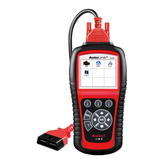
3. Using the Scan Tool 3.1 Tool Description OBD II CONNECTOR – Connects the scan tool to the vehicle’s Data Link Connector (DLC). LCD DISPLAY – Indicates test results. FUNCTION BUTTONS – Corresponds with “buttons” on screen for executing commands. ESC BUTTON –... -
Page 12: Specifications
LEFT SCROLL BUTTON – When look up DTC definitions, moves to previous character and views additional information on previous screens if DTC definition covers more than one screen; views previous screen or previous frames of recorded data. It is also used to view previous trouble code when viewing DTCs. -
Page 13: Accessories Included
Storage Temperature: -20 to 70° C (-4 to 158 F° ) External Power: 8.0 to 18.0 V power provided via vehicle battery Dimensions: Length Width Height 199 mm (7.83”) 104.5 mm (4.11”) 37.5 mm (1.48”) Weight: 0.28kg(without wire) 0.484kg(with wire) 3.3 Accessories Included User’s Manual -- Instructions on tool operations. -
Page 14: System Setup
Power up the scan tool , and wait for the Main Screen to appear.(Figure 3.1) Figure 3.1 3.6 System Setup The System Setup functions allow you to adjust default settings and view information about the scan tool. Language: Selects the desired language. Unit of measure: Sets the unit of measure to English or Metric. - Page 15 Figure 3.2 Language Setup English is the default language. From System Setup screen, use the UP/DOWN scroll button and LEFT/RIGHT scroll button to select Language, and press the OK button. Use the UP/DOWN scroll button to select the desired language and press the OK button to save your selection and return to previous screen.
- Page 16 From Unit of Measure screen, use the LEFT/RIGHT scroll button to select the desired unit of measurement. (Figure 3.4 ) Figure 3.4 Press the OK button to save your selection and return to previous menu. Or, press the ESC button to exit without saving. Beep Set ...
- Page 17 Press the OK button to save your selection and return to previous menu. Or, press the ESC button to exit without saving. Key Test The Key Test function checks if the keyboard is working properly. From System Setup screen, use the UP/DOWN scroll button and LEFT/RIGHT scroll button to select Key Test, and press the OK button.
-
Page 18: Vehicle Coverage
When completed, press the ESC button to exit. About The About function allows viewing of some important information such as serial number and software version number of the scanner. From System Setup screen, use the UP/DOWN scroll button and LEFT/RIGHT scroll button to select About and press the OK button, wait for the About screen to appear. -
Page 19: Product Troubleshooting
“OBD II Certified”. Additionally, Government regulations mandate that all OBD II compliant vehicles must have a “common” sixteen-pin Data Link Connector (DLC). For your vehicle to be OBD II compliant it must have a 16-pin DLC (Data Link Connector) under the dash and the Vehicle Emission Control Information Label must state that the vehicle is OBD II compliant. - Page 20 If the scan tool freezes, then an exception occurs or the vehicle’s ECU (Engine Control Unit) is too slow to respond to requests. You need to do the following to reset the tool: Reset the scan tool. Turn the ignition off and wait for about 10 seconds. Turn the ignition back to on and continue the testing.
-
Page 21: Playback Data
4. Playback Data The Playback Data function allows viewing data from last test recorded by the scan tool. 4.1 Reviewing Data Use the LEFT/RIGHT scroll button to select Playback from Main Screen (Figure 3.1), and press the OK button. Wait for the Review Data screen to appear. -
Page 22: Deleting Data
If no data from previously tested vehicle is recorded, a message “No data available!” shows on the screen. Review selected data on screen. Vehicle Specification Vehicle: Mustang Engine Type: Other Capacity: 3.8L Transmission: Manual Fuel Type: Gasoline Emission Level: Federal Emission VIN:1FAFP40462F100819 PrefSuf:2R3APB VersionID:4612... -
Page 23: Obdii Diagnostics
5. OBDII Diagnostics The OBD II Diagnostics function is a fast-access option that allows you to carry out a quick test on the engine system of OBD II vehicles. When more than one vehicle control module is detected by the scan tool, you will be prompted to select the module where the data may be retrieved. -
Page 24: Read Codes
vehicle. Contact your local distributor manufacturer’s customer service department for assistance. 7) View a summary of system status (MIL status, DTC counts, Monitor status) on screen. (Figure 5.1 ) Press ESC button for Diagnostic Menu (Figure 5.3) to come up. System Status MIL Status Codes Found... - Page 25 more than a specified amount of key-cycles. These codes will cause the control module to illuminate the malfunction indicator light (MIL) when emission-related fault occurs. Pending Codes are also referred to as “maturing codes” or “continuous monitor codes”. They indicate problems that the control module has detected during the current or last driving cycle but are not considered serious yet.
- Page 26 Read Codes 1.Stored Codes 2.Pending Codes 3.Permanent Codes Figure 5.4 If there is not any Diagnostic Trouble Code, the display indicates “No (pending) codes are stored in the module!” Wait a few seconds or press any key to return to previous screen. NOTE: Permanent Codes function is available for merely vehicles supporting the CAN protocols.
-
Page 27: Erasing Codes
If the manufacturer of your vehicle is not listed, use the UP/DOWN scroll button to select Other and press the OK button. 5.2 Erase Codes CAUTION: Erasing the Diagnostic Trouble Codes may allow the scan tool to delete not only the codes from the vehicle’s on-board computer, but also “Freeze Frame”... - Page 28 If you press Yes function key or OK button, a warning message will come up asking your confirmation. (Figure 5.7) Erase Codes DTCs and Freeze Data will be lost Do you wish to continue? Figure 5.7 Press the OK button to confirm. ...
-
Page 29: Live Data
Press any button to return to Diagnostic Menu. 5.3 Live Data In this function, you can not only read the live data but also record data for later review. Viewing Data The View Data function allows viewing of live or real time PID data of vehicle’s computer module(s). - Page 30 …………………Live Data 1. Complete List 2. Custom List Figure 5.11 2) View live PIDs on the screen. Use the UP/DOWN scroll button for more PIDs if additional information is available on more than one page.( Figure 5.12) Complete List Numbers of DTCs Fuel system 1 status Fuel system 2 status Calculated load value...
- Page 31 Figure 5.13 If the “Merge Graph” on the bottom appears when a PID is selected to view, merged graph information is available. (Figure 5.14) NOTE: Merge Graph can be used to compare two related parameters in graphic mode, which is especially convenient in the Custom List option where you could select two interacted parameter to merge and see their relationship.
- Page 32 3) Press the ESC button to return to previous menu. B. Viewing Custom List 1) To view customized PID data, use the UP/DOWN scroll button to select Custom List from Live Data menu and press the OK button.( Figure 5.11) 2) Use the UP/DOWN scroll button to move up and down to the desired items and click Select button to confirm.
- Page 33 Custom List Numbers of DTCs Fuel system 1 status Pause Graphics Save Figure 5.16 Use the ESC button to return to previous menu. Recording Data The Record Data function allows recording vehicle modules’ Parameter Identification (PID) data help diagnose intermittent vehicle problems. You could save data files to the SD card and then use the Playback function to view the saved files.
- Page 34 If you record live data under graph mode, following screen shows: Figure 5.18 NOTE: The scan tool can only playback text data even though the data is saved in graphic mode. When there is not enough memory space, a warning message prompting to delete previously recorded data.
-
Page 35: Freeze Frame
You may review the saved data in Playback function. Press ESC button to exit. 5.4 Freeze Frame Freeze Frame Data allows the technician to view the vehicle’s operating parameters at the moment a DTC (Diagnostic Trouble Code) is detected. For example, the parameters may include engine speed (RPM), engine coolant temperature (ECT), or vehicle speed sensor (VSS) etc. -
Page 36: Retrieving I/M Readiness Status
If you don’t want to save the freeze frame data, press ESC button to return to previous screen. 5.5 Retrieving I/M Readiness Status I/M Readiness function is used to check the operations of the Emission System on OBD2 compliant vehicles. It is an excellent function to use prior to having a vehicle inspected for compliance to a state emissions program. - Page 37 If the vehicle supports both types of tests, then both types will be shown on the screen for selection. (Figure 5.21) …………… I/M Readiness 1.Since DTCs Cleared 2.This Drive Cycle Figure 5.21 4) Use the UP/DOWN scroll button, as necessary, to view the status of the MIL light (“ON”...
- Page 38 NCAT -- NOx Aftertreatment Monitor BP -- Boost Pressure System Monitor EGS -- Exhaust Gas Sensor Monitor PM -- PM Filter Monitor Since DTCs cleared MIL Status Misfire Monitoring Fuel system monitoring Comprehensive component monitoring Catalyst monitoring Heated catalyst monitor Figure 5.22 5) If the vehicle supports readiness test of “This Drive Cycle”, a...
-
Page 39: O2 Monitor Test
5.6 O2 Monitor Test OBD2 regulations set by SAE require that relevant vehicles monitor and tests on the oxygen (O2) sensors to identify problems related to fuel efficiency and vehicle emissions. These tests are not on-demand tests and they are done automatically when engine operating conditions are within specified limits. -
Page 40: On-Board Monitor Test
…………….O2 Monitor Test………….. The selected mode is not supported! Press any key to continue Figure 5.25 View test results of selected O2 sensor. (Figure 5.26) … ……… .O2 Bank1 Sensor2 Rich-Lean Threshd V Lean-Rich Threshd V Low for Switch (V) High for Switch (V) Rich-Lean Threshd S Lean-Rich Threshd S... - Page 41 and a current value for each monitor. By comparing the current value with the minimum and maximum value, the scan tool will determine if it is OK. Use the UP/DOWN scroll button to select On-Board Monitor Test from Diagnostic Menu and press the OK button. (Figure 5.3) Wait a few seconds while the scan tool validates the PID MAP.
- Page 42 On-Board Monitor Test 1. Test $01 Data 2. Test $03 Data 3. Test $10 Data 4. Test $21 Data 5. Test $22 Data 6. Test $25 Data Figure 5.28 If the vehicle under test does not support the mode, an advisory message will be displayed on the screen.
-
Page 43: Component Test
View test data on screen. Test $01 Data Module Test Value 0400 Min Limit 0200 Max Limit ---- Status Figure 5.31 For CAN-equipped vehicles, test results displayed can be as below: Flow Test Module Test Value 0.10 Min Limit 0.00 Max Limit 95.0... - Page 44 2) Wait for the scan tool to display the Component Test menu. Component Test 1.EVAP Sys. Leak Test Figure 5.33 3) If the test has been initiated by the vehicle, a confirmation message will be displayed on the screen. Component Test Command Sent! Press any key to continue Figure 5.34...
-
Page 45: Viewing Vehicle Information
.....Component Test The selected mode is not supported Press any key to continue Figure 5.35 4) Wait a few seconds or press any key to return to previous screen. 5.9 Viewing Vehicle Information The Vehicle Info. function enables retrieval of Vehicle Identification (VIN), Calibration... -
Page 46: Modules Present
Vehicle Info. 1.Vehicle ID Number 2.Caibration ID 3.Cal. Verf. Number Figure 5.37 If the vehicle does not support this mode, a message shows on the display warning that the mode is not supported. 4) From Vehicle Info. menu, use the UP/DOWN scroll button to select an available item to view and press the OK button. -
Page 47: Dtc Lookup
Modules Present Protocol SAE J1850 PWM Save Figure 5.39 3) Select Save to save the modules data and return to previous menu. Or press ESC button to exit. 5.11 DTC Lookup The DTC Lookup function allows user to search definitions of DTC stored in built-in DTC library. - Page 48 Input Dialog Box P0005 Do you want to save and continue? Figure 5.41 Press Yes or OK button to proceed. The scan tool will display DTC definition as below. Trouble Codes P0005 Fuel Shutoff Valve A Control Circuit/Open Save Figure 5.42 ...
-
Page 49: Abssrs Testing
Malfunction Indicator Light (MIL) to turn on. NOTE: Autel accepts no responsibility for any accident or injury arising from servicing the ABS/SRS systems. When interpreting DTCs retrieved from the vehicle, always follow the manufacturer’s recommendation for repair. -
Page 50: Abssrs Diagnostic Testing
6.1 AbsSrs Diagnostic Testing Please follow these steps to finish ABS/SRS system diagnostic testing procedure: Turn the ignition on but do not start the engine. Turn on the scan tool and wait for the Main Screen to appear. Select AbsSrs icon in the Main Screen. (Figure 3.1) Select a specific vehicle manufacture’s regional coverage. - Page 51 There are two ways for users to perform diagnostic testing system either automatically or manually: A. Auto Start New Session To finish this procedure, please follow these steps (Taking GM as an example): Select the GM Logo from the car make screen. (Figure 6.2) Use the UP/DOWN scroll button to select the correct Model Year(s) from the menu as shown in Figure 6.3.
- Page 52 Vehicle Type 1.Chevrolet 2.Buick 3.Cadillac 4.Holden Figure 6.5 Follow screen entries to select the correct engine model. (Figure 6.6) Camara 1.3.6 L(LFX) 2.6.2 L(L99) 3.6.2 L(LS3) 4.6.2 L(LSA) Figure 6.6 NOTE: You may not need to make all the selections, or have to select other features.
- Page 53 3.6 L(LFX) 1.SupplementalInflatableRestraint 2.Electronic Brake Control Module Figure 6.7 To review the Diagnostic Trouble Codes (DTC) or Module ID Information saved in the Supplemental Inflatable Restraint or Electronic Brake Control Module system, use the UP/DOWN scroll button to select the desired item. Then press OK button to continue.
- Page 54 To finish this procedure, please follow these steps (Taking Ford as an example): Select the Ford Logo from the car make screen. (Figure 6.2) Use the UP/DOWN scroll button to select the Manual Vehicle Entry option from the DAS menu. (Figure 6.9) 1.Start New Session 2.Manual Vehicle Entry 3.Vehicle selection...
- Page 55 Tear Tag AEB2 INPUT DATA Finish Show Figure 6.11 Follow the onscreen instruction to save the information and continue on the procedure, or select the No option or press ESC button to exit without saving. Choose a specific car series from the Vehicle Specification menu.(Figure 6.12) Vehicle Specification 1.
- Page 56 INPUT DATA 1FDXE45S65HB01520 Finish Show Figure 6.13 [ Finish ] : After entering a new value, use this key to save the value to the VIN. [ Show ] : Press this key to pop up a soft keyboard to facilitate your input.
- Page 57 NOTE: The data you input must be in the reasonable range, which is defined by the preset values in VIN. If you enter a data out of range, the tool will display a warning message.(Figure 6.15) Figure 6.15 Follow screen instruction to save vehicle information in the Input Dialog Box and Vehicle Specification sections by selecting Yes option, or No option to exit without saving.
- Page 58 Select An Option 1.Control Unit 2.Vehicle Information Figure 6.17 11) Select the Control Unit entry to enter the System Menu option screen, and choose the desired Control Module entry for DTC information stored in the vehicle’s on-board computer. (Figure 6.18) System Menu 1.ABS/TCS—Anti-Lock Brake/ Traction Control Module...
-
Page 59: Print And Update
7. Print and Update 7.1. Print Data The Print Data function allows printing out diagnostic data recorded by the scan tool or customized test reports by connecting the scan tool to a PC or laptop with the USB cable supplied. ... -
Page 60: Software Update
The selected data will display on the textbox of Printer. By selecting the function keys on the right, you could execute the following operations: Print – Print all data in the textbox to a printer connected to your computer. ... - Page 61 Section 3.6 System Setup. Figure 7.2 Update Procedure Autel frequently releases software updates that you can download. The Update feature makes it very easy to determine and get exactly what you need. Install PC Suit through the included CD, or download the applications in our website: www.auteltech.com or our...
- Page 62 Remove the TF card from the scan tool. Connect the TF card to computer with a card reader Run the update option in PC Suit software. Wait for the Log In window to pop up. (Figure 7.3) Figure 7.3 Put in the user name and password and wait for the Update window to display.
- Page 63 Generally, there are two ways to update programs: Batch updating Select the programs that you would update by clicking on the check boxes next to those items. Then click the Update Selected Items button on the right side of screen. ...
- Page 64 To resume updating process, click the INSTALL button in the line again. The progress will resume from the break point. When the downloading is completed, the downloaded program will be installed automatically. The new version will replace the old version.
- Page 65 cancel the action. The deleted program will automatically add to the end of program list in the UPDATE page in case you would like to install again. Theoretically, all programs in latest versions will be automatically compatible with the older versions, but if your scan tool do have a compatible problem and want to retrieve the older version for some programs, you may need to delete them first then install the older version again.
-
Page 66: Warranty And Service
8. Warranty and Service 8.1. Limited One Year Warranty Autel warrants to its customers that this product will be free from all defects in materials and workmanship for a period of one (1) year from the date of the original purchase, subject to the following terms and...
Need help?
Do you have a question about the AutoLink AL619EU and is the answer not in the manual?
Questions and answers