Advertisement
Quick Links
Advertisement

Subscribe to Our Youtube Channel
Related Manuals for Hanwha Techwin Wisenet HCB-7000


Summary of Contents for Hanwha Techwin Wisenet HCB-7000
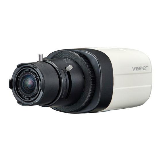
- Page 1 High Resolution Box Camera User Manual HCB-7000 HCB-7000PH...
- Page 2 High Resolution Box Camera User Manual Copyright ©2017 Hanwha Techwin Co., Ltd. All rights reserved. Trademark Each of trademarks herein is registered. The name of this product and other trademarks mentioned in this manual are the registered trademark of their respective company.
- Page 3 Before operating the camera, confirm the camera model and correct input power voltage. To help you understand this manual thoroughly, we'll introduce our model description. ■ HCB-7000 SERIES • NTSC MODEL • PAL MODEL HCB-7000N HCB-7000P HCB-7000PH ■ MODEL DESCRIPTION •...
- Page 4 safety information CAUTION RISK OF ELECTRIC SHOCK. DO NOT OPEN CAUTION: TO REDUCE THE RISK OF ELECTRIC SHOCK, DO NOT REMOVE COVER (OR BACK) NO USER SERVICEABLE PARTS INSIDE. REFER SERVICING TO QUALIFIED SERVICE PERSONNEL. This symbol indicates that dangerous voltage consisting a risk of electric shock is present within this unit.
- Page 5 9. If this product fails to operate normally, contact the nearest service center. never disassemble or modify this product in any way. (Hanwha Techwin is not liable for problems caused by unauthorized modifications or attempted repair.) 10.
- Page 6 safety information FCC Statement This device complies with part 15 of the FCC Rules. Operation is subject to the following two conditions : 1) This device may not cause harmful interference, and 2) This device must accept any interference received including interference that may cause undesired operation.
- Page 7 important safety instructions Read these instructions. Keep these instructions. Heed all warnings. Follow all instructions. Do not use this apparatus near water. Clean only with dry cloth. Do not block any ventilation openings. Install in accordance with the manufacturer’s instructions. Do not install near any heat sources such as radiators, heat registers, or other apparatus (including amplifiers) that produce heat.
- Page 8 Apparatus shall not be exposed to dripping or splashing and no objects filled with liquids, such as vases, shall be placed on the apparatus Hanwha Techwin cares for the environment at all product manufacturing stages, and is taking measures to provide customers with more environmentally friendly products.
- Page 9 contents INTRODUCTION Features Components and Accessories Overview Lens CONNECTION Connecting to Monitor Connecting to Power Control via RS-485 Interface Using Coaxial Communications CAMERA OPERATION Menu Configuration Menu Setup TROUBLESHOOTING Troubleshooting SPECIFICATIONS Specifications Dimension English_9...
- Page 10 introduction FEATURES y High Resolution It uses 4.1-megapixel CMOS device to provide a high-definition quality of 2560x1440 resolution. y Excellent Sensitivity The built-in high sensitivity COLOR CMOS produces a clear image. - Color : 0.16Lux (F1.2, 1/30sec) B/W : 0.009Lux (F1.2, 1/30sec) y D-WDR If an object has a large variance between bright and dark areas, it will keep bright areas bright and make selected dark areas bright, so that the overall brightness can be...
- Page 11 COMPONENTS AND ACCESSORIES Check if the following items are included in the product package. Camera Quick Manual Sheets lens mount English_11...
- Page 12 introduction OVERVIEW Front View ❶ Tripod Mounting Bracket Screw Hole : ` Used to fix the camera on a bracket. The screw sizes for this hole are as follows. 1/4"-20 UNC (20 THREAD) L:4.5mm±0.2mm (ISO standard), or 0.178" (ASA standard) Lens adaptor : IInstall this if you use the lens.
- Page 13 Rear View <HCB-7000> VIDEO POWER <HCB-7000PH> POWER VIDEO English_13...
- Page 14 introduction Function Setup switch Display the menu on the screen and move the cursor to four directions to confi rm ststus or after changing a selected item. Switching between AHD and CVBS modes: Press the SET button for more than 5 seconds.
- Page 15 LENS The lens is not supplied with this camera. Purchase a lens suitable for your environment. This camera accepts the auto iris lens and both C-and CS-mount lens. To use the functions of this camera effectively it is recommended that a DC type Auto Iris lens is used.
- Page 16 introduction When Using a C/CS-Mount lens (Sold separately) Before installing a lens, identify whether the lens to be installed is a C-Mount or CS-Mount. This camera is set for a CS-Mount Lens by default. To install a C-Mount Lens, a simple modification is required.
- Page 17 y When Using a C-Mount Lens 1. Remove the protective glass cover at the front of this product and turn the C-Mount Adapter clockwise to install it. C-Mount Adapter C-Mount Adapter C-Mount Adapter 2. Turn the C-Mount lens clockwise to install it.
- Page 18 connection CONNECTING TO MONITOR Refer to the following figure to connect monitors through DVR. ALARM NETWORK BACKUP POWER AHD DVR VIDEO POWE R Monitor HCB-7000 y As the connecting method varies with the instruments, refer to the manual supplied with the instrument. y Only connect the cable when the power is turned off.
- Page 19 When the resistance value of copper wire is at [20°C(68°F)] Copper wire size (AWG) #24 (0.22mm #22 (0.33mm #20 (0.52mm #18 (0.83mm Resistance value(Ω/m) 0.078 0.050 0.030 0.018 Voltage Drop (V/m) 0.028 0.018 0.011 0.006 y As shown in the table above, voltage decreases as the wire gets longer. Therefore use of an excessively long adaptor output line for connection to the camera may affect the performance of the camera.
- Page 20 connection USING COAXIAL COMMUNICATIONS y Coaxial Communications System y OSD Control method CAMERA CONTROLLER MENU/ENTER OSD KEY UP KEY JOYSTICK UP DOWN DOWN KEY JOYSTICK DOWN LEFT LEFT KEY JOYSTICK LEFT RIGHT RIGHT KEY JOYSTICK RIGHT ALARM NETWORK BACKUP POWER - Video Cable The camera's video output port is connected to the monitor with a BNC coaxial cable, shown below.
- Page 21 camera operation MENU CONFIGURATION MAIN SETUP ◦ ◦ VIDEO FORMAT CVBS ◦ ◦ D-WDR ◦ ◦ ◦ INDOOR OUTDOOR WHITE BAL ◦ ◦ AWC → SET MANUAL ◦ ◦ ◦ BRIGHTNESS LENS SHUTTER EXPOSURE ◦ ◦ ◦ RETURN ◦ ◦ ◦...
- Page 22 camera operation MAIN SETUP 1. VIDEO FORMAT Select the Change the status function using 2. D-WDR using the Function the Function Setup switch. 3. WHITE BAL Setup switch. 4. EXPOSURE 5. BACKLIGHT 6. SPECIAL 7. EXIT SAVE 1. Press the Function Setup switch. y Main SETUP menu is displayed on the monitor screen.
- Page 23 D-WDR If an object has a large variance between bright and dark areas, it will keep bright areas bright and make selected dark areas bright, so that the overall brightness can be maintained. 1. When the SETUP menu screen is MAIN SETUP displayed, select ‘D-WDR’...
- Page 24 camera operation y INDOOR : Select this when the color temperature is between 4,500K and 8,500K. Automatically adjusts the camera color for optimization to the indoor environment. y MANUAL : Select this to fine-tune White WB MANUAL Balance manually. Set White ...
- Page 25 - Manual : The shutter does not automatically move but is fixed to the maximal degree in this mode. Some lenses may not work properly, depending on the setting of the BRIGHTNESS LEVEL. y SHUTTER : You can select the shutter. - MIN : 1/30 ~ 1/12000 - MAX : 1/60 ~ 1/12000(NTSC) , 1/50 ~ 1/12000(PAL) - A.FLK : Select this when you experience picture flicker, this happen when there is...
- Page 26 camera operation y USER BLC : Enables a user to select a desired area on a picture and view that area more clearly. BLC SETUP - LEVEL : Adjusts the brightness level of a ▶ LEVEL M I D D L E monitoring area.
- Page 27 SPECIAL 1. When the SETUP menu screen is MAIN SETUP displayed, select ‘SPECIAL’ by using 1. VIDEO FORMAT the Function Setup switch so that the 2. D-WDR arrow indicates ‘SPECIAL’ . 3. WHITE BAL 2. Select a desired mode using the 4.
- Page 28 camera operation y IMAGE ADJ ❶MM I f the SPECIAL menu screen is IMAGE SETUP displayed, use the Function Setup ▶ GAMMA USER switch so that the arrow indicates PED LEVEL IIIIIIIIIIIIIIIIIIII ‘IMAGE ADJ’ . COLOR GAIN IIIIIIIIIII IIIIIIIII ❷MM S elect a desired mode using the 4.
- Page 29 - AUTO : The mode is switched AUTO SETUP to ’Color‘ in a normal ▶ BURST MODE environment, but switches DURATION NORMAL to ’B/W‘ mode when DWELL TIME 30 SEC ambient illumination is low. RETURN To set up the switching time for AUTO mode, press the Function Setup switch.
- Page 30 camera operation - AREA : You can select up to 2 PRIVACY areas. - MODE : Determines whether to use the area selected in the AREA. - MASK COLOR : Determine area color. You can select Green, Yellow, Red, Blue, Black, White, Gray.
- Page 31 Depending on the shape of an object, there can be errors in size detection. If the camera shoots an object a short distance away, the motion detection function can be degraded. In the following cases, motion detection event performance can be degraded or malfunctions can occur.
- Page 32 troubleshooting TROUBLESHOOTING If you have trouble operating your camera, refer to the following table. If the guidelines do not enable you to solve the problem, contact an authorized technician. Problems Troubleshooting Nothing appears on the screen. y Check that the power cord and line connection between the camera and AHD DVR are properly connected.
- Page 33 specifications SPECIFICATIONS HCB-7000N/P HCB-7000PH Video Imaging Device 1/3” 4M CMOS Total Pixels 2720(H) x 1536(V) Effective Pixels 2688(H) x 1520(V) Scanning System Progressive Scan Color : 0.16Lux (F1.2, 1/30sec) Min. Illumination B/W : 0.009Lux (F1.2, 1/30sec) S / N Ratio 52dB (AGC off, Weight on) Video Output BNC(AHD), additional CVBS for installation...
- Page 34 specifications HCB-7000N/P HCB-7000PH Video Transmission 500m(5C2V Coaxial Cable) Distance Environmental Operating Temperature / -10°C ~ +55°C (+14°F ~ +131°F) / Less than 90% RH Humidity Electrical Dual ( 24VAC±10%/300mA & Input Voltage/Current AC 230V, 50/60Hz, 70mA 12VDC±10%/300mA ) Power Consumption Max.
- Page 35 DIMENSION <HCB-7000> Unit: mm English_35...
- Page 36 specifications <HCB-7000PH> Unit: mm 36_ specifications...
- Page 37 MEMO...
- Page 38 Head Office 6, Pangyo-ro 319 beon-gil, Bundang-gu, Seongnam-si, Gyeonggi-do, 463-400 Rep. of KOREA Tel : +82.70.7147.8753 Fax : +82.31.8018.3740 www.hanwha-security.com Hanwha Techwin America 500 Frank W. Burr Blvd. Suite 43 Teaneck, NJ 07666 Toll Free +1.877.213.1222 Direct +1.201.325.6920 Fax +1.201.373.0124 www.hanwha-security.com...
Need help?
Do you have a question about the Wisenet HCB-7000 and is the answer not in the manual?
Questions and answers