Table of Contents
Advertisement
Advertisement
Table of Contents

Related Manuals for Hanwha Techwin WiseNet HCB-6001


Summary of Contents for Hanwha Techwin WiseNet HCB-6001
- Page 1 High Resolution Box Camera User Manual HCB-6001...
-
Page 2: User Manual
High Resolution Box Camera User Manual Copyright ©2017 Hanwha Techwin Co., Ltd. All rights reserved. Trademark Each of trademarks herein is registered. The name of this product and other trademarks mentioned in this manual are the registered trademark of their respective company. - Page 3 Before operating the camera, confirm the camera model and correct input power voltage. To help you understand this manual thoroughly, we'll introduce our model description. ■ HCB-6001 SERIES • NTSC MODEL • PAL MODEL HCB-6001N HCB-6001P ■ MODEL DESCRIPTION • HCB-6001X _ SIGNAL SYSTEM • SIGNAL SYSTEM N →...
- Page 4 safety information CAUTION RISK OF ELECTRIC SHOCK. DO NOT OPEN CAUTION : TO REDUCE THE RISK OF ELECTRIC SHOCK, DO NOT REMOVE COVER (OR BACK) NO USER SERVICEABLE PARTS INSIDE. REFER SERVICING TO QUALIFIED SERVICE PERSONNEL. This symbol indicates that dangerous voltage consisting a risk of electric shock is present within this unit.
- Page 5 6. Do not place conductive objects (e.g. screwdrivers, coins, metal parts, etc.) or containers filled with water on top of the camera. doing so may cause personal injury due to fire, electric shock, or falling objects. 7. Do not install the unit in humid, dusty, or sooty locations. doing so may cause fire or electric shock.
-
Page 6: Fcc Statement
safety information FCC Statement This device complies with part 15 of the FCC Rules. Operation is subject to the following two conditions : 1) This device may not cause harmful interference, and 2) This device must accept any interference received including interference that may cause undesired operation. -
Page 7: Important Safety Instructions
important safety instructions Read these instructions. Keep these instructions. Heed all warnings. Follow all instructions. Do not use this apparatus near water. Clean only with dry cloth. Do not block any ventilation openings. Install in accordance with the manufacturer’s instructions. Do not install near any heat sources such as radiators, heat registers, or other apparatus (including amplifiers) that produce heat. - Page 8 Apparatus shall not be exposed to dripping or splashing and no objects filled with liquids, such as vases, shall be placed on the apparatus Hanwha Techwin cares for the environment at all product manufacturing stages, and is taking measures to provide customers with more environmentally friendly products.
-
Page 9: Table Of Contents
contents INTRODuCTION Features Components and Accessories Overview Lens CONNECTION Connecting to Monitor Connecting to Power Control via RS-485 Interface Using Coaxial Communications CAMERA OPERATION Menu Configuration Menu Setup TROuBLESHOOTING Troubleshooting SPECIFICATIONS Specifications Dimension English_9... - Page 10 introduction FEATuRES y High Resolution Use of a 2 mega pixel CMOS device provides clear pictures with a horizontal resolution of 1000. y Excellent Sensitivity The built-in high sensitivity COLOR CMOS produces a clear image. - Color: 0.15Lux(F1.2) B/W: 0.09Lux(F1.2) y SSNR4 (Samsung Super Noise Reduction) Function High performance DSP Chip removes noises of GAIN resulting from the low light level and shows a vivid, high definition video even in the dark place.
-
Page 11: Components And Accessories
y Communication Coaxial and RS-485 communication methods are supported. - Coaxial Communications: ACP(AHD Coax Protocol), TCP(TVI Coax Protocol), CCP(CVI Coax Protocol), COAX-C(CVBS Coax Protocol) - RS-485 Communications : SAMSUNG-T/SAMSUNG-E/PELCO-D/PELCO-P/BOSCH/ HONEYWELL y OSD The camera’s OSD is complimented by 16 languages. - English, Japanese, Spanish, French, Portuguese, Korean, German, Italian, Russian, Polish, Czech, Romanian, Serbian, Swedish, Danish, Turkish. -
Page 12: Overview
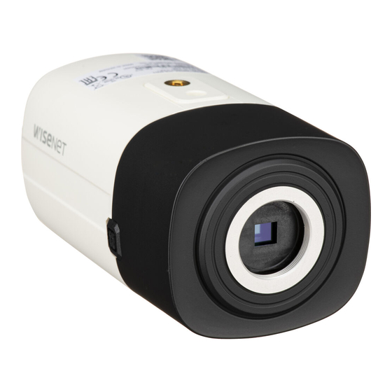
introduction OvERvIEw Front view ❶ Tripod Mounting Bracket Screw Hole : ` Used to fix the camera on a bracket. The screw sizes for this hole are as follows. 1/4"-20 UNC (20 THREAD) L:4.5mm±0.2mm (ISO standard), or 0.197" (ASA standard) Lens adaptor : IInstall this if you use the lens. -
Page 13: Rear View
Rear view VIDEO POWER 1 : 485+ 2 : 485- 3 : D/N 4 : MD 5 : GND Function Setup switch Press the Function Setup switch briefly to display the menu screen. After the menu is displayed on the screen, move the cursor <up/down/left/right> to select the desired item or to change the value or status. -
Page 14: Lens
introduction LENS The lens is not supplied with this camera. Purchase a lens suitable for your environment. This camera accepts the auto iris lens and both C-and CS-mount lens. To use the functions of this camera effectively it is recommended that a DC type Auto Iris lens is used. - Page 15 when using a C/CS-Mount lens (Sold separately) Before installing a lens, identify whether the lens to be installed is a C-Mount or CS-Mount. This camera is set for a CS-Mount Lens by default. To install a C-Mount Lens, a simple modification is required.
- Page 16 introduction y when using a C-Mount Lens 1. Remove the protective glass cover at the front of this product and turn the C-Mount Adapter clockwise to install it. C-Mount Adapter 2. Turn the C-Mount lens clockwise to install it. C-Mount Adapter 3.
-
Page 17: Connecting To Power
connection CONNECTING TO MONITOR Refer to the following figure to connect monitors through DVR. ALARM NETWORK BACKUP POWER AHD DVR VIDEO POWER 1 : 485+ 2 : 485- 3 : D/N 4 : MD 5 : GND HCB-6001 Monitor y As the connecting method varies with the instruments, refer to the manual supplied with the instrument. -
Page 18: Control Via Rs-485 Interface
connection When the resistance value of copper wire is at [20°C(68°F)] Copper wire size (AWG) #24 (0.22mm #22 (0.33mm #20 (0.52mm #18 (0.83mm Resistance value(Ω/m) 0.078 0.050 0.030 0.018 Voltage Drop (V/m) 0.028 0.018 0.011 0.006 y As shown in the table above, voltage decreases as the wire gets longer. Therefore use of an excessively long adaptor output line for connection to the camera may affect the performance of the camera. -
Page 19: Using Coaxial Communications
uSING COAXIAL COMMuNICATIONS y Coaxial Communications System y OSD Control method CAMERA CONTROLLER MENU/ENTER OSD KEY UP KEY JOYSTICK UP DOWN DOWN KEY JOYSTICK DOWN LEFT LEFT KEY JOYSTICK LEFT RIGHT RIGHT KEY JOYSTICK RIGHT ALARM NETWORK BACKUP POWER - Video Cable The camera's video output port is connected to the monitor with a BNC coaxial cable, shown below. -
Page 20: Menu Setup
camera operation MENu CONFIGuRATION MAIN SETUP ◦ ◦ ◦ CVBS VIDEO FORMAT ◦ ◦ ◦ ◦ BASIC DAY/NIGHT BACKLIGHT PROFILE ◦ ◦ ◦ INDOOR USER ◦ ◦ D-WDR ◦ ◦ ◦ OUTDOOR INDOOR WHITE BAL ◦ ◦ AWC → SET MANUAL ◦... -
Page 21: Video Format
MAIN SETuP 1. vIDEO FORMAT Select the Change the status 2. PROFILE BASIC function using using the Function 3. D-wDR the Function Setup switch. 4. wHITE BAL Setup switch. 5. EXPOSuRE 6. BACKLIGHT 7. SPECIAL 8. SIMPLE FOCuS 9. EXIT SAvE 1. - Page 22 camera operation PROFILE 1. When the SETUP menu screen is MAIN SETuP displayed, select ‘PROFILE’ by using the 1. vIDEO FORMAT Function Setup switch so that the arrow 2. PROFILE BASIC indicates ‘PROFILE’ . 3. D-wDR 2. Select a desired mode using the 4.
- Page 23 D-WDR If an object has a large variance between bright and dark areas, it will keep bright areas bright and make selected dark areas bright, so that the overall brightness can be maintained. 1. When the SETUP menu screen is displayed, select ‘D-WDR’ by using the Function Setup switch so that the arrow indicates ‘D-WDR’...
- Page 24 camera operation y MANuAL : Select this to fine-tune White wB MANuAL Balance manually. Set White 1. RED GAIN IIIIIIIIII IIIIIIIIII Balance first by using the ATW 2. BLuE GAIN IIIIIIII IIIIIIIIIIII or AWC mode. After that button 3. RETuRN to MANUAL mode, fine-tune the White Balance and the Function Setup switch.
- Page 25 Some lenses may not work properly, depending on the setting of the BRIGHTNESS LEVEL. y SHuTTER : You can select the shutter. - MIN : 1 ~ 1/12000 - MAX : 1/60 ~ 1/12000(NTSC) , 1/50 ~ 1/12000(PAL) - A.FLK : Select this when you experience picture flicker, this happen when there is a clash with the installed lighting frequency.
- Page 26 camera operation y uSER BLC : Enables a user to select a desired area on a picture and BLC SETuP view that area more clearly. ▶ LEvEL M I D D L E - LEVEL : Adjusts the brightness level of a IIII IIIIIIIIIIIIIIII monitoring area.
- Page 27 If the white balance menu is set to manual, then HLC performance can be limited. If you use the defog and HLC functions at the same time, saturation can occur in a bright environment. Because there can be a difference in the effectiveness of HLC according to the amount of light area in the screen, optimize the installation angle for the best HLC performance.
- Page 28 camera operation ➎MM E nter a title, move the cursor to ‘POS’ and press the FRONT DOOR Function Setup switch. The entered title appears on the screen. Select the position to display the title on the screen by using the Function Setup switch and press the Function Setup switch.
- Page 29 - RET PKT : Determines whether to send a command back to the controller device when a communication control command is sent to the camera. - COAX : You can select whether to use COAX communication. - RETURN : Return to the SPECIAL menu. y IMAGE ADJ ❶MM I f the SPECIAL menu screen is IMAGE SETuP...
- Page 30 camera operation - AUTO : The mode is switched AuTO SETuP to ’Color‘ in a normal ▶ BuRST MODE environment, but switches DuRATION NORMAL to ’B/W‘ mode when DwELL TIME 30 SEC ambient illumination RETuRN is low. To set up the switching time for AUTO mode, press the Function Setup switch.
- Page 31 - Manual : Depending on the defog DEFOG level set by the user, adjust ▶ LEvEL MIDDLE the clarity of image. (LOW, RETuRN MIDDLE, HIGH) - OFF : Released state If the defog mode is set to Auto, and if the amount of fog is reduced, the function level will be also reduced.
- Page 32 camera operation ` MODE : Determine whether to use the selected area. ` MASK : Under Motion Detection, If you don’t want to see mosaic image on the screen, you may turn MASK OFF. If you wants to see mosaic image, please turn it on. ` TRANSPARENCY: Adds or removes transparency from the masking area.
- Page 33 - Severe snow, rain and wind. Sunset or sunrise - If the size is greater than the max size or smaller than the min size, motion is not detected. To avoid false detection caused by noises, set the max/min detection size suitable for the installation environment.
- Page 34 camera operation EXIT Select a desired EXIT mode using the Function Setup switch depending on the camera purpose. y SAvE : Save the current settings and exit the MAIN SETUP menu. y NOT SAvE : Do not save the current settings and exit the MAIN SETUP menu. y RESET : Revert camera to factory settings.
- Page 35 troubleshooting Troubleshooting If you have trouble operating your camera, refer to the following table. If the guidelines do not enable you to solve the problem, contact an authorized technician. Problems Troubleshooting Nothing appears on the screen. y Check that the power cord and line connection between the camera and AHD DVR are properly connected.
- Page 36 specifications SPECIFICATIONS HCB-6001N HCB-6001P video Imaging Device 1/2.8" 2M CMOS Total Pixels 1,945(H) x 1,109(V) 2.16M pixels Effective Pixels 1,945(H) x 1,097(V) 2.13M pixels Scanning System Progressive Scan Color: 0.15Lux(F1.2) Min. Illumination B/W: 0.09Lux(F1.2) S / N Ratio 52dB (AGC off, Weight on) video Output BNC(AHD / TVI / CVI / CVBS Selectable) Resolution...
- Page 37 HCB-6001N HCB-6001P Reverse Off / H-Rev / V-Rev / HV-Rev Profile Basic, Day & Night, Backlight, ITS, Indoor, User Intelligent video Analytics Not support Alarm MD output 1,External D/N 1 Remote control interface Coaxial, RS-485 Coax : ACP(AHD Coax Protocol), TCP(TVI Coax Protocol), CCP(CVI Coax Protocol), Protocol COAX-C(CVBS Coax Protocol) RS-485 : SAMSUNG-T/SAMSUNG-E/PELCO-D/PELCO-P/BOSCH/HONEYWELL...
-
Page 38: Dimension
DIMENSION Unit: mm 38_ specifications... - Page 39 MEMO...
- Page 40 Head Office 6, Pangyo-ro 319 beon-gil, Bundang-gu, Seongnam-si, Gyeonggi-do, 463-400 Rep. of KOREA Tel : +82.70.7147.8753 Fax : +82.31.8018.3740 www.hanwha-security.com Hanwha Techwin America 500 Frank W. Burr Blvd. Suite 43 Teaneck, NJ 07666 Toll Free +1.877.213.1222 Direct +1.201.325.6920 Fax +1.201.373.0124 www.hanwha-security.com...
Need help?
Do you have a question about the WiseNet HCB-6001 and is the answer not in the manual?
Questions and answers