
Subscribe to Our Youtube Channel
Related Manuals for Hanwha Techwin Wisenet XNB-6002


Summary of Contents for Hanwha Techwin Wisenet XNB-6002
- Page 1 NETWORK CAMERA User Manual XNB-6002/ SLA-T1080FA/SLA-T2480A/SLA-T2480VA/SLA-T2880BA/ SLA-T4680A/SLA-T4680VA/SLA-T4680DA/SLA-T4680DSA...
- Page 2 Network Camera User Manual Copyright ©2022 Co., Ltd. All rights reserved. Hanwha Techwin Trademark Each of trademarks herein is registered. The name of this product and other trademarks mentioned in this manual are the registered trademark of their respective company. Restriction Copyright of this document is reserved.
- Page 3 overview IMPORTANT SAFETY INSTRUCTIONS 22. Installing or using the product in water can cause serious damage to the product. 23. This device has been verified using STP cable. The use of appropriate GND grounding and STP cable is recommended to effectively protect your product and property from transient voltage, thunderstroke, 1.
- Page 4 overview Class construction Please read the following recommended safety precautions carefully. An apparatus with CLASS construction shall be connected to a MAINS socket outlet with a ~ Do not place this apparatus on an uneven surface. protective earthing connection. ~ Do not install on a surface where it is exposed to direct sunlight, near heating equipment or heavy cold area.
-
Page 5: Table Of Contents
CONTENTS OVERVIEW Important Safety Instructions WEB VIEWER Connecting to the Camera Recommended PC Specifications Password setting Recommended Micro SD/SDHC/SDXC Login Memory Card Specifications Camera Web Viewer Setup NAS recommended specs Video output What’s Included (XNB-6002) What’s Included (Lens module - Optional) At a Glance APPENDIX Troubleshooting... -
Page 6: Recommended Pc Specifications
overview RECOMMENDED PC SPECIFICATIONS NAS RECOMMENDED SPECS ~ CPU : Intel(R) Core(TM) i7 3.4 GHz or higher ~ Recommended capacity : 200GB or higher is recommended. ~ RAM : 8G or higher ~ For this camera, you are recommended to use a NAS with the following manufacturer’s specs. ~ Recommended browser: Chrome Recommended products : QNAP NAS, Synology NAS ~ Supported browsers: Chrome, Safari, Firefox, MS Edge(chromium based) -
Page 7: What's Included (Xnb-6002)
WHAT’S INCLUDED (XNB-6002) WHAT’S INCLUDED (LENS MODULE - OPTIONAL) Please check if your camera and accessories are all included in the product package. This is a lens module separately sold that is mounted to XNB-6002. (As for each sales country, accessories are not the same.) Please check if your camera and accessories are all included in the product package. - Page 8 overview Model Name Appearance Item Name Quantity Description Model Name Appearance Item Name Quantity Description Lens Module Lens Module Quick Guide Quick Guide (Optional) (Optional) Tapping Screw Used for installation on the wall or ceiling Lens module bracket Use this for lens module installation SLA-T2480VA Cable tie Use this for organizing the cable...
- Page 9 Model Name Appearance Item Name Quantity Description Model Name Appearance Item Name Quantity Description Double-sided tape Used to fix brackets on glass Lens Module Used to remove pollutants on surfaces Quick Guide Surface cleaner where brackets are attached (Optional) SLA-T2880BA Used as tapping screw covers for floor Screw cover installation...
- Page 10 overview Model Name Appearance Item Name Quantity Description Model Name Appearance Item Name Quantity Description Lens Module Lens Module Quick Guide Quick Guide (Optional) (Optional) Tapping Screw Used for installation on the wall or ceiling SLA-T4680VA Lens module bracket Use this for lens module installation Cable tie Use this for organizing the cable SLA-T4680A...
- Page 11 Model Name Appearance Item Name Quantity Description Lens Module Quick Guide (Optional) Lens module bracket Use this for lens module installation SLA-T4680DA/ SLA-T4680DSA Torx L wrench Used to remove and attach the bracket Used to fix the direction of the lens Screw module Cable to connect lens...
-
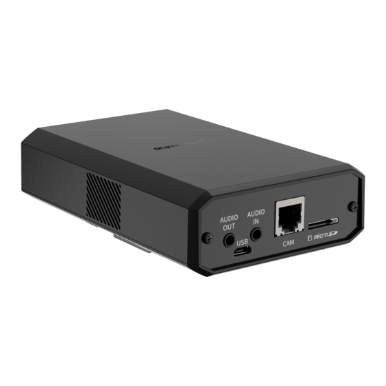
Page 12: At A Glance
overview AT A GLANCE DC 12V 4 3 2 1 NETWORK VIDEO RESET Front of the main unit Rear of the main unit GND : 1, 2 ALARM OUT : 3 ALARM IN : 4 AUDIO AUDIO Item Description Item Description Port to connect the Wi-Fi dongle. - Page 13 Appearance of lens module <SLA-T1080FA> <SLA-T2480A> <SLA-T2480VA> <SLA-T4680VA> Item Description Lens Module This lens module is used to shoot video. Main unit connection This terminal is connected to the main unit through the cable to connect the lens module. terminal <SLA-T4680A>...
-
Page 14: Installation & Connection
installation & connection INSTALLATION 2. Install the bracket on the wall by using the two tapping screws that are included in the product. Precautions before installation Ensure you read out the following instructions before installing the camera: ~ Organize the cable separately in order to prevent excessive burden on the lens module while the camera is installed (within 1m from the lens module ). - Page 15 Install lens module (SLA-T1080FA) Install lens module (SLA-T2480A/SLA-T4680A) 1. Drill a hole which the lens is passed through at the location where you want to 1. Use two screws provided or remove protective film to use the double- install it. sided tape on the bottom side of the lens module bracket to install the lens module bracket.
- Page 16 installation & connection Install lens module (SLA-T2480VA/SLA-T4680VA) Installing the lens module in the main unit Connect the lens module cable to the [CAM] port on the side of the main unit. 1. Make a hole for the lens module at the spot where you want to install it. Connect the lens module and turn it on.
- Page 17 Connect lens module cable to lens module Adjust the length of the cable for connecting the lens module The length of the cable for connecting the main unit and lens module can be adjusted. Please follow the 1. Unscrew the back cover by turning it counterclockwise. steps in the correct order to adjust the length of the cable for connection: Be sure to remove the back cover first and assemble/disassemble the RJ45 1.
-
Page 18: Inserting/Removing A Micro Sd Card
installation & connection AUDIO AUDIO INSERTING/REMOVING A MICRO SD CARD Removing a Micro SD card Gently press down on the exposed end of the memory card as shown in the diagram to eject the memory card from the slot. Disconnect the power cable from the camera before inserting the Micro SD card. When it rains or the humidity is high, insertion or ejection of a Micro SD card is not recommended. -
Page 19: Connecting With Other Device
CONNECTING WITH OTHER DEVICE Power Supply Use the screwdriver to connect each line (+, –) of the power cable to the corresponding power port of the camera. WiFi dongle If the power sources for PoE and DC 12 V are simultaneously turned on, the device power will be supplied by both of PoE and DC 12V. - Page 20 installation & connection Connecting WiFi Connecting to Audio Input/Output Camera Setup 1. Connect OTG adapter (5-pin) and WiFi dongle to the micro USB port. Speaker Smartphone Setup 1. Install the Wisenet Installation application. Microphone 2. Select the camera SSID after turning on the WiFi. 3.
- Page 21 Connecting to the I/O port box To connect the alarm out Connect the Alarm I/O cable to the corresponding port of the port box. If devices (e.g., flashing light and siren) that exceed the voltage and current specifications are connected by using the open collector method, it may cause malfunction.
-
Page 22: Network Connection And Setup
network connection and setup You can set up the network settings according to your network configurations. CONNECTING THE CAMERA DIRECTLY TO A DHCP BASED DSL/CABLE MODEM CONNECTING THE CAMERA DIRECTLY TO LOCAL AREA NETWORKING Connecting to the camera from a local PC in the LAN INTERNET DC 12V 4 3 2 1... -
Page 23: Using Device Manager
If using a Broadband Router ~ IP Address : Enter an address falling in the IP range provided by the Broadband Router. Device manager program can be downloaded from <Support>-<Online Tools> menu at Hanwha Techwin website (http://www. ex) 192.168.1.2~254, 192.168.0.2~254, hanwha-security.com). -
Page 24: Manually Registering Camera
network connection and setup Configuring Dynamic IP AUTOMATICALLY CONFIGURING IP Receive IP address from DHCP 1. Click the camera from the list that you want to automatically ~ Example of the Dynamic IP environment configure the IP. XNB-6002 - If a Broadband Router, with cameras connected, is assigned an IP address by the DHCP server 2. -
Page 25: Port Range Forward (Port Mapping) Setup
PORT RANGE FORWARD (PORT MAPPING) SETUP Setting up Port Range Forward for several network cameras ~ You can set a rule of Port Forwarding on the Broadband Router device through its configuration web page. If you have installed a Broadband Router with a camera connected, you must set the port range forwarding on the ~ A user can change each port using the camera setting screen. -
Page 26: Connecting To The Camera From A Shared Local Pc
network connection and setup CONNECTING TO THE CAMERA FROM A SHARED LOCAL PC 1. Run device manager. It will scan for connected cameras and display them as a list. 2. Double-click a camera to access. The Internet browser starts and connects to the camera. Access to the camera can also be gained by typing the camera’s IP address in the address bar of the Internet browser. -
Page 27: Connecting To The Camera
web viewer CONNECTING TO THE CAMERA Connecting via Bonjour 1. Run the client or operating system in support of the Bonjour protocol. Normally, you would 2. Click the camera name for search. In the Mac operating system, click the camera name searched from the Bonjour tab of Safari. 1. -
Page 28: Password Setting
web viewer PASSWORD SETTING CAMERA WEB VIEWER SETUP When you access the product for the first time, you must register the 1. Click the [Setup ( )] icon. login password. 2. The Settings window appears. 3. You can configure settings for the camera’s basic information, video, audio, network, event, analysis, and system over the network. -
Page 29: Troubleshooting
appendix TROUBLESHOOTING PROBLEM SOLUTION PROBLEM SOLUTION ~ Verify the settings in the following sequence: When an Windows 10 user accesses <Motion detection> of <Analytics> is ~ This is what happens when microphone driver has been set to Realtek driver. the web viewer through Chrome set to <Enable>, but no notification A. - Page 30 Operation of this equipment in a residential area is likely to cause harmful interference in which case the user will be required to correct the interference at his own expense. Hanwha Techwin cares for the environment at all product manufacturing stages, and is taking measures to provide customers with more environmentally friendly products.
Need help?
Do you have a question about the Wisenet XNB-6002 and is the answer not in the manual?
Questions and answers