Table of Contents
Advertisement
Quick Links
Advertisement
Table of Contents

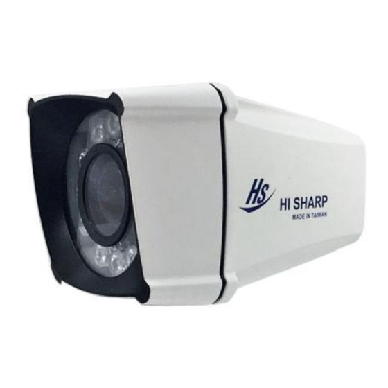
Summary of Contents for Hi Sharp HS-4IN1-T022CQ
- Page 1 HD Analogue Camera_ Manual...
-
Page 2: Table Of Contents
Contents SAFETY PRECAUTIONS ..........3 Specification ..............4 Product contents ............. 5 Product overview ............6 Dimension ................ 7 COC (control over coaxial) function ......8 OSD function ..............9 OSD Menu ..............10 Connection ..............15... -
Page 3: Safety Precautions
SAFETY PRECAUTIONS Please read before using The lightning flash with arrowhead symbol, within an equilateral triangle, is intended to alert the user to the presence of insulated dangerous Voltage within the product’s enclosure that may be sufficient magnitude to constitute risk of electrical shock to persons. The exclamation point within an equilateral triangle is intended to alert the user to the presence of important operation and maintenance (servicing) instructions in the literature accompanying the appliance. -
Page 4: Specification
Specification 1/3” SONY CMOS : 2.0 Mega Image unit Resolution 1920(H) x 1080(V) Video Output AHD / CVI / TVI / CVBS Synchronization Internal Scanning System 2:1 interlace S/N Ratio More than 55 dB ( AGC OFF) Electronic Shutter Auto 1/60 (1/50) ~ 1/50,000 sec Min. -
Page 5: Product Contents
Product contents Item Figure Screw × 8 Anchor × 4 Wrench × 1 Bracket × 1 Adaptor (1A) × 1 (Optional) -
Page 6: Product Overview
Product overview ① ② ④ ③ ⑤ ⑥ ⑧ ⑦ Item Description Item Description ① ⑤ Power cable (DC 12 V± 10%) Camera ② ⑥ BNC cable Bracket ③ ⑦ OSD button ZOOM ④ ⑧ Bracket hole FOCUS ※ Lens adjustment : ⑦... -
Page 7: Dimension
Dimension Unit : mm... -
Page 8: Coc (Control Over Coaxial) Function
COC (control over coaxial) function ① Enable the channel which you want to configure, and choose COC (control over coaxial) function under PTZ Protocol page. ② Click the right button of the mouse, choose PTZ Control. ③ Click ” Iris + “ to open OSD menu. Icon Description Open the OSD menu of camera / Enter... -
Page 9: Osd Function
OSD function Suppose you buy a product with OSD function, please refer to the following description: Figure Description Open the OSD menu of camera / Enter ※ Push the button about 5 sec to switch NTSC/PAL Direction button, in order to choose the item that you want to config. -
Page 10: Osd Menu
OSD Menu Notice : ”(xxx)”means (default value) LENS MANUAL (Default) EXPOSURE SHUTTER 1/30,1/60,FLK,1/240,1/480,1/1000,1/2000,1/5000,1/10000,1/50000, X2,X4,X6,X8,X10,X15,X20,X25,X30,AUTO (AUTO) 0-15 (13) SENS-UP AUTO SENS-UP X2,X4,X6,X8,X10,X15,X20,X25, (Default) X30,(X2) RETURN RET,SAVE & END BRIGHTNESS 1-100 (50) D-WDR LEVEL 0-8 (5) RETURN RET,SAVE & END AUTO (Default) DEFOG OFF (Default) AUTO... - Page 11 RETURN RET,SAVE & END WHITE BAL ATW (Default) AWC →SET INDOOR OUTDOOR MANUAL BLUE 0-100 (63) 0-100 (43) RETURN RET,SAVE & END D →N(AGC) DAY& AUTO 1-255 (168) D →N(DELAY) NIGHT 0-60 (5) N →D(AGC) 1-255 (80) N →D(DELAY) 0-60 (5) RETURN RET,SAVE &...
- Page 12 MOTION OFF (Default) SELECT AREA1,AREA2,AREA3,AREA4 (AREA1) DISPLAY POSITION, (Default) SIZE,RET,AGAIN SENSITIVITY 0-100 (64) COLOR GREEN,BLUE,WHITE,RED (GREEN) TRANS 0.00/1.00/0.75/0.25 (1.00) ALARM VIEW ALL,OFF, BLOCK, TYPE OUTLINE (ALL) OFF,ON (ON) VIEW ALARM OFF,ON (ON) TIME 1-15 (3) RETURN RET,SAVE & END DEFAULT RETURN RET,SAVE &...
- Page 13 DEFECT LIVE DPC ON (Default) 0-255 (70) LEVEL LEVEL 0-100 (50) RETURN RET,SAVE & END WHITE DPC ON (Default) POSITION, POS/SIZE SIZE,RET,AGAIN CLOSE THE IRIS START THEN PRESS ENTER DPC VIEW ON, OFF (OFF) LEVEL 0-60 (15) 0-14 (14) X2,X4,X6,X8,X10, SENS-UP X15,X20,X25,X30 (X8)
- Page 14 0.70,0.75,0.80,0.85,0.90,0.95, 1.00 (USER) BLUE GAIN 0~100 (50) RED GAIN 0~100 (50) RETURN RET,SAVE & END BLUE GAIN 0~100 (50) RED GAIN 0~100 (50) RETURN RET,SAVE & END ON, OFF (ON) VIDEO. OUT NTSC,PAL RETURN RET,SAVE & END SAVE & END,NOT SAVE,RESET(SAVE & END) EXIT...
-
Page 15: Connection
Connection Paste the sticker on the wall location that you want to place. Lock the screws to fix the bracket. - Page 16 Make sure the connection is tightened. Lock the bottom screws as well.
- Page 17 Connect BNC cable and power cable. BNC cable Power cable ※NOTICE : If necessary, please install 4 anchors before the second step. 85-CQ02HS-A502G-B...


Need help?
Do you have a question about the HS-4IN1-T022CQ and is the answer not in the manual?
Questions and answers