Advertisement
Quick Links
Tel +1 (717) 767-6511
Fax +1 (717) 764-0839
www.redlion.net
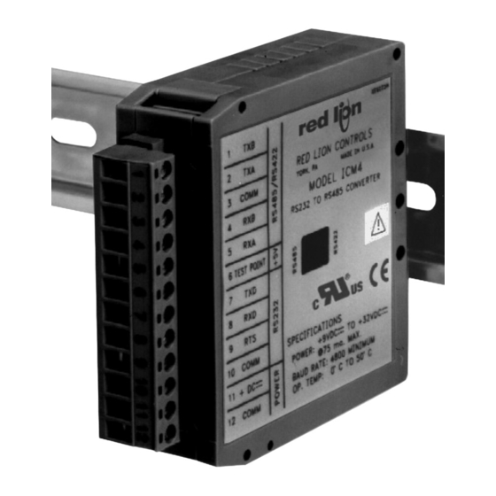
MODEL ICM4 - SERIAL CONVERTER MODULE (RS232C/RS485)
DESCRIPTION
The ICM4 Serial Converter Module provides the capability of interfacing
equipment with RS485 serial communications to equipment with RS232
communications. Data format of the RS232 and RS485 equipment must be
the same.
For full duplex (RS422), the DIP switch on the side of the module must be in
the RS422 position. For half duplex (RS485), the DIP switch must be in the
RS485 position. In half duplex mode, the RS485 driver is enabled using the
leading edge of the first character transmitted (RXD input). After the last
character transmits, the converter waits one character time (at 9600 baud) to
disable the RS485 driver.
There are 3 LED's that can be viewed from the front of the converter module.
A green power LED indicates power is on, a red RS232 TXD LED flashes when
the module is transmitting, and a green RS232 RXD LED flashes when the
module is receiving.
An external DC power source (+9 to 32 VDC) is required to power the ICM4.
The external power source and serial communications connections are made via
a 12 position removable terminal block located on the front of the module.
The unit is equipped with a universal mounting foot for attachment to
standard DIN style mounting rails, including top hat profile rail according to
EN50022 - 35 x 7.5 and 35 x 15, and G profile rail according to EN50035 - G32.
SAFETY SUMMARY
All safety related regulations, local codes and instructions that appear in the
manual or on equipment must be observed to ensure personal safety and to
prevent damage to either the instrument or equipment connected to it. If
equipment is used in a manner not specified by the manufacturer, the protection
provided by the equipment may be impaired.
Read complete instructions prior to
installation and operation of the unit.
DIMENSIONS In inches (mm)
CAUTION: Risk of Danger.
ALLOWS COMMUNICATIONS BETWEEN RS232 CONTROL
EQUIPMENT AND PRODUCTS WITH RS485 SERIAL
COMMUNICATIONS
WIDE DC INPUT POWER RANGE (+9 to 32 VDC)
HALF DUPLEX (RS485) AND FULL DUPLEX (RS422)
LED INDICATION FOR RXD, TXD, and POWER
UNIVERSAL MOUNTING FOOT FOR DIN RAIL INSTALLATION
UL Recognized Component,
File # E179259
SPECIFICATIONS
1. POWER: +9 to 32 VDC @ 75 mA maximum. Above 26 VDC, derate max.
operating temperature to 40°C. Power supply must be Class 2 or SELV rated.
2. RS232 VOLTAGES:
Receive Data Pin: ± 30 VDC max.
Mark Condition: ≤ 0.8 VDC
Space Condition: ≥ 2.4 VDC
Transmit Data Pin:
Mark Condition: −8 VDC (typ.)
Space Condition: +8 VDC (typ.)
3. RS485 VOLTAGES:
Differential Output Voltage: ± 5 VDC max. under no load
Differential Input Voltage: ± 5 VDC max.
Mark Condition: ≤ −0.2 VDC
Space Condition: ≥ +0.2 VDC
RS485 Drive Capability: Up to 32 RS485 receivers connected in parallel.
RS485 Drive Disable Time: 4 msec. max.
4. MAXIMUM CABLE LENGTH:
RS232: 50 feet
RS485: 4000 feet
5. BAUD RATE: 9600 min., 19200 max.
6. CERTIFICATIONS AND COMPLIANCES:
SAFETY
UL Recognized Component, File #E179259, UL3101-1, CSA C22.2 No.
1010-1
Recognized to U.S. and Canadian requirements under the Component
Recognition Program of Underwriters Laboratories, Inc.
IECEE CB Scheme Test Certificate # US/5141B/UL,
CB Scheme Test Report # 01ME11540-0702001
Issued by Underwriters Laboratories, Inc.
IEC 61010-1, EN 61010-1: Safety requirements for electrical
equipment for measurement, control and laboratory use, Part 1.
ELECTROMAGNETIC COMPATIBILITY
Immunity to EN 50082-2
Electrostatic discharge
Electromagnetic RF fields
Fast transients (burst)
RF conducted interference
Simulation of cordless telephone ENV 50204
Emissions to EN 50081-1
RF interference
Refer to EMC Installation Guidelines for additional information.
1
Bulletin No. ICM4-D
Drawing No. LP0416
Released 3/07
EN 61000-4-2
Level 2; 4 Kv contact
Level 3; 8 Kv air
EN 61000-4-3
Level 3; 10 V/m
80 MHz - 1 GHz
EN 61000-4-4
Level 4; 2 Kv I/O
Level 3; 2 Kv power
EN 61000-4-6
Level 3; 10 V/rms
150 KHz - 80 MHz
Level 3; 10 V/m
900 MHz ± 5 MHz
200 Hz, 50% duty cycle
EN 55022
Enclosure class B
Advertisement

Related Manuals for red lion ICM4


Summary of Contents for red lion ICM4
- Page 1 Space Condition: ≥ +0.2 VDC module is receiving. An external DC power source (+9 to 32 VDC) is required to power the ICM4. RS485 Drive Capability: Up to 32 RS485 receivers connected in parallel. The external power source and serial communications connections are made via RS485 Drive Disable Time: 4 msec.
- Page 2 1. Connect shield drain wire to earth ground. interference. Install them near the power entry point of the enclosure. The 2. Place DIP switch on the side of the ICM4 in the 422 position. following EMI suppression devices (or equivalent) are recommended: 3.
- Page 3 Notes: 1. Connect shield drain wire to earth ground. 2. Place DIP switch on the side of the ICM4 in the 485 position. 3. The transmit and receive data lines of the ICM4 should be wired together. TYPICAL CONNECTION FOR SINGLE UNIT...
- Page 4 The Company disclaims all liability for any affirmation, promise or representation with respect to the products. The customer agrees to hold Red Lion Controls harmless from, defend, and indemnify RLC against damages, claims, and expenses arising out of subsequent sales of RLC products or products...
Need help?
Do you have a question about the ICM4 and is the answer not in the manual?
Questions and answers