Table of Contents
Advertisement
Quick Links
Tel +1 (717) 767-6511
Fax +1 (717) 764-0839
www.redlion.net
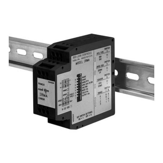
MODEL IRMA DC -
DESCRIPTION
The IRMA accepts an RTD or resistance input and converts it into a voltage
or current output. The output is linearly proportional to the temperature or
resistance input. This output is ideal for interfacing to indicators, chart
recorders, controllers, or other instrumentation equipment.
The IRMA is DC powered. The DC power input is isolated from the signal
input and analog output. The unit scales the analog output proportionally to the
RTD or resistance input signal. The analog output may be configured for one of
the following: 0 to 20 mA, 4 to 20 mA, or 0 to 10 VDC. Making the signal
conversion with the IRMA to a current output signal, makes the signal less
susceptible to noise interference and allows accurate transmission over long
distances. The 3-Way isolation allows the use of grounded RTD's which can
provide additional noise reduction benefits.
The IRMA uses an eight position DIP switch to accomplish the input sensor
configuration, range selection, and unit calibration. A simple range setting
technique (Field Calibration) is used so the actual input signal adjusts the output
for scaling. This technique eliminates the need for potentiometers which are
vulnerable to changes due to vibration.
The unit is equipped with a universal mounting foot for attachment to
standard DIN style mounting rails, including top hat rail (T) according to EN 50
022 - 35
7.5 and 35
15, and (G) profile according to EN 50 035 - G 32.
DIMENSIONS In inches (mm)
3.12
(79.2)
MC2234X
ORDERING INFORMATION
MODEL NO.
DESCRIPTION
IRMA
Intelligent RTD Module
INTELLIGENT RTD MODULE WITH ANALOG OUTPUT
1.08
(27.5)
POWER
IRMA
ERROR
PART NUMBER
IRMA3035
USER PROGRAMMABLE INPUT
(RTD alpha = 0.00385 (DIN 43760), alpha = 0.00392, or resistance)
MICROPROCESSOR CONTROLLED
SIMPLE ADJUSTABLE RANGE SETTING (Using Input Signal)
RTD BREAK DETECTION
MOUNTS ON "T" AND "G" STYLE DIN RAILS
3-WAY ELECTRICAL ISOLATION (POWER/INPUT/OUTPUT)
MULTIPLE ANALOG OUTPUTS (0 to 20 mA, 4 to 20 mA, and 0 to
10 VDC)
WIDE OPERATING TEMPERATURE RANGE (-25°C to 75°C)
LED INDICATION (POWER & MEMORY ERROR)
9 to 32 VDC POWERED
SAFETY SUMMARY
All safety related regulations, local codes and instructions that appear in the
manual or on equipment must be observed to ensure personal safety and to
prevent damage to either the instrument or equipment connected to it. If
equipment is used in a manner not specified by the manufacturer, the protection
provided by the equipment may be impaired.
CAUTION: Read complete instructions prior
to installation and operation of the unit.
SPECIFICATIONS
1. POWER: 9 to 32 VDC; 1.75 W. 200 mA max. current. The power supply
must have 400 mA for 200 msec. surge capacity.
2. INPUT: RTD 2, 3, or 4 wire, 100 ohm platinum, alpha = 0.00385
(DIN 43760), alpha = 0.00392, or resistance [selectable via DIP switches].
Excitation: 0.170 mA nominal
Lead resistance: Less than 0.5°C with 15 ohms max. per lead
Note: There is no lead compensation for 2 wire input. Field calibration
should be performed with equivalent series resistance.
3. OUTPUT: All output signals scaled linearly using temperature or resistance
input. Unit is shipped set for the 4 to 20 mA output. 4 to 20 mA or 0 to 20
mA selected via internal jumper.
Voltage Output Compliance:
0 to 10 VDC across min. 1 K load (10 mA)
20 mV peak to peak max. ripple (for frequencies up to 120 Hz)
Current Output Compliance:
0 to 20 mA through max. 600 load (12 VDC)
4 to 20 mA through max. 600 load (12 VDC)
15 mV peak to peak max. ripple across 600 load (for frequencies up to
120 Hz)
4. RTD BREAK DETECTION: Nominal values shown in the following order:
(0 to 20 mA, 4 to 20 mA, and 0 to 10 VDC).
Upscale: 22.9 mA, 22.5 mA, and 11.5 VDC
Downscale: -0.5 mA, 3.5 mA, and -0.4 VDC
5. RESPONSE TIME: 400 msec. (to within 99% of final value w/step input;
typically, response is limited to response time of probe.)
6. TEMPERATURE EFFECTS:
Temperature Coefficient: 0.025% of input range per C
7. DIELECTRIC WITHSTAND VOLTAGE: 1500 VAC for 1 minute
Working Voltage: 50 VAC
Power input to Signal input, Power input to Signal output, & Signal input to
Signal output.
1
Bulletin No. IRMA-E
Drawing No. LP0437
Released 02/10
Advertisement
Table of Contents

Related Manuals for red lion IRMA DC


Summary of Contents for red lion IRMA DC
-
Page 1: Specifications
Drawing No. LP0437 Released 02/10 Tel +1 (717) 767-6511 Fax +1 (717) 764-0839 www.redlion.net MODEL IRMA DC - INTELLIGENT RTD MODULE WITH ANALOG OUTPUT USER PROGRAMMABLE INPUT (RTD alpha = 0.00385 (DIN 43760), alpha = 0.00392, or resistance) ... -
Page 2: Function Descriptions
8. RANGE & ACCURACY: (12 Bit resolution) BLOCK DIAGRAM Accuracy: ( 0.075% Range + 0.1°C [Conformity]) at 23°C after 45 min. warm-up, conforming to ITS-90. 0.170mA Note: RTD Conformity does not apply to resistance input. For best accuracy, calibration should be performed under operating conditions. PROCESS CONTROL Relative Humidity: Less than 85% RH (non-condensing) -
Page 3: Wiring Connections
WIRING CONNECTIONS POWER Connect DC power to terminals #10 and #12 observing proper polarity. Be All conductors should meet MONITORING INSTRUMENT certain DC power is within the 9 to 32 VDC specifications. voltage and current ratings for VOLTAGE METER each terminal. Also, cabling POWER LED should conform to appropriate CURRENT METER... -
Page 4: Field Calibration
CALIBRATION PROCEDURES 1.0 Field Calibration RTD temperature to resistance conversion table Field Calibration scales the selected output to a temperature or resistance input. This procedure assigns an input value to the low end and an input value to the high end. The microprocessor handles configuring the output so it is Temperature alpha alpha... -
Page 5: Basic Calibration
2.0 Basic Calibration The Basic Calibration should only be performed with an ambient temperature between MONITORING INSTRUMENT 21°C and 29°C. The Basic Calibration was performed on the unit at the factory and VOLTAGE METER generally does not need to be done again. This procedure initializes the unit by calibrating CURRENT METER the input. -
Page 6: Installation
RTD signal loss problem VDC+ VDC- from long cable runs. The IRMA DC powered unit is mounted at the machine and uses the local 24 VDC for power. The signal loss problem is solved using MACHINE'S POWER SUPPLY the 4 to 20 mA analog output for the long cable run to the master control room. - Page 7 This Page Intentionally Left Blank...
-
Page 8: Limited Warranty
The Company disclaims all liability for any affirmation, promise or representation with respect to the products. The customer agrees to hold Red Lion Controls harmless from, defend, and indemnify RLC against damages, claims, and expenses arising out of subsequent sales of RLC products or products...
Need help?
Do you have a question about the IRMA DC and is the answer not in the manual?
Questions and answers