Table of Contents
Advertisement
Quick Links
Tel +1 (717) 767-6511
Fax +1 (717) 764-0839
www.redlion.net
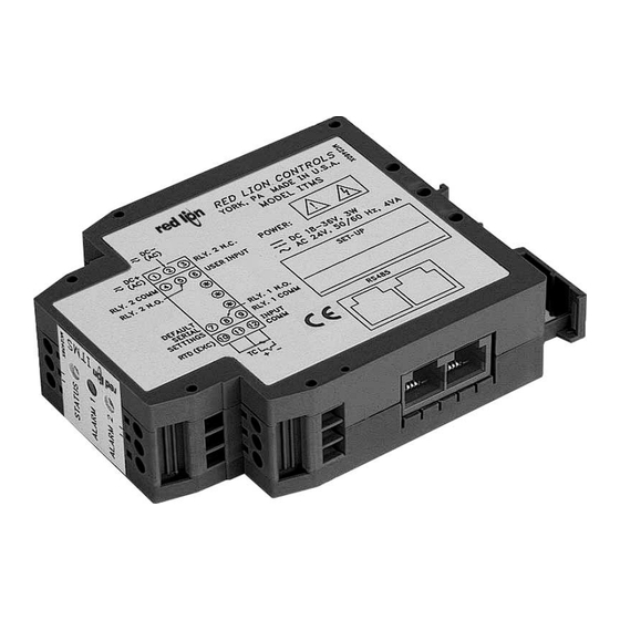
MODEL ITMS - INTELLIGENT TEMPERATURE TO MODBUS CONDITIONER W/ ALARMS
GENERAL DESCRIPTION
The ITMS4037 Intelligent Temperature to MODBUS™ Conditioner with
Alarms accepts a wide range of temperature sensors (thermocouple and RTD
elements), and converts the signal into a register format that can be read using
either ASCII or RTU MODBUS protocol.
The ITMS allows a choice of either Fahrenheit or Celsius readout with 0.1 or
1 degree of resolution. An offset value can be programmed to scale the input
signal to meet most process requirements. Additionally, two setpoint values can
be entered for dual relay process monitoring alarms.
The ITMS is programmed with Windows™ based SFIMS software. The
software allows configuration, calibration, and storage of ITMS program files.
Additionally, all setup parameters can be interrogated and modified through
MODBUS register and coil commands.
The RS485 port allows the ITMS to be multidropped, with Baud rates up to
38400. The CBPRO007 programming cable converts the RS232 port of a PC to
RS485, and is terminated with an RJ-11 connector. The bidirectional capability
of the CBPRO007 allows it to be used as a permanent interface cable as well as
a programming cable.
The ITMS's two relay alarms can be configured independently for absolute
high or low acting with balanced or unbalanced hysteresis. Alarm 2 can also be
configured for deviation and band alarms. In these modes, Setpoint 2 tracks
Setpoint 1. Adjustable alarm trip delays can be used for delaying output
response. The alarms can be programmed for Automatic or Latching. Latched
alarms can be reset with a serial command or a user input. A standby feature
suppresses the alarm during power-up until the temperature stabilizes outside
the alarm region. Standby eliminates power-up tripping for low acting alarms.
A user input can be used to set and reset non-latching alarms. The output relays
can also be manually controlled with register commands.
The module's high density packaging and DIN rail mounting saves time and
panel space. The module is equipped with a universal mounting foot for
attachment to standard DIN rails, including top hat (T) profile or G profile rail.
ORDERING INFORMATION
MODEL
DESCRIPTION
ITMS
Temperature to MODBUS Conditioner w/Alarms
SFIMS
PC Configuration Software for Windows
CBPRO
Programming Interface Cable
Cable RJ11 to Unterminated 7 foot length
CBJ
Cable RJ11 to RJ11 6 inch jumper
RJ Connector to Terminal Adapter
Courtesy of Steven Engineering, Inc. ● 230 Ryan Way, South San Francisco, CA 94080-6370 ● General Inquiries: (800) 670-4183 ● www.stevenengineering.com
TEMPERATURE TO MODBUS CONVERSION
ACCEPTS THERMOCOUPLE, RTD, mV OR RESISTANCE
SIGNALS
PROCESSOR BASED SCALING
PC CONFIGURATION SOFTWARE
DUAL SETPOINT RELAY ALARMS
FOUR WAY SIGNAL ISOLATION
SAFETY SUMMARY
All safety related regulations, local codes and instructions that appear in the
manual or on equipment must be observed to ensure personal safety and to
prevent damage to either the instrument or equipment connected to it. If
equipment is used in a manner not specified by the manufacturer, the protection
provided by the equipment may be impaired.
CAUTION: Read complete
instructions prior to installation
and operation of the unit.
DIMENSIONS In inches (mm)
PART NUMBER
ITMS4037
SFIMS
CBPRO007
CBJ11A07
CBJ11BD5
DRRJ11T6
1
UL Recognized Component,
File # E179259
CAUTION: Risk of electric shock.
Bulletin No. ITMS-B
Drawing No. LP0494
Released 1/07
Advertisement
Table of Contents

Related Manuals for red lion ITMS4037


Summary of Contents for red lion ITMS4037
- Page 1 File # E179259 GENERAL DESCRIPTION SAFETY SUMMARY The ITMS4037 Intelligent Temperature to MODBUS™ Conditioner with All safety related regulations, local codes and instructions that appear in the Alarms accepts a wide range of temperature sensors (thermocouple and RTD manual or on equipment must be observed to ensure personal safety and to elements), and converts the signal into a register format that can be read using prevent damage to either the instrument or equipment connected to it.
-
Page 2: Specifications
SPECIFICATIONS 11. MEMORY: Nonvolatile E PROM retains all programmable parameters. 12. ENVIRONMENTAL CONDITIONS: POWER: 18-36 VDC, 3.0 W max. or 24 VAC, 10%, 50/60 Hz, 4 VA max. ± Operating Temperature Range: -20 to +65 °C 2. INPUT: Storage Temperature Range: -40 to +85 °C Sample Rate: 67 msec. -
Page 3: Led Functionality
MODULE ISOLATION LED FUNCTIONALITY The ITMS features “4-way” signal isolation. The 4-way isolation is a CONDITION GREEN LED 2 RED LEDS combination of optical, transformer and relay barriers, providing common mode voltage (CMV) isolation to 1.5 KV for 1 minute between input, RS485, and Power Applied ———... -
Page 4: Step 1 Wiring The Module
There are two RJ-11 connectors located on the bottom for paralleling communications. For single device communications, either connector can be used. When used in conjunction with Red Lion Control Paradigm HMI products, reverse A+ and B- wiring. RJ11... -
Page 5: Step 3 Programming - Getting Started
STEP 3 PROGRAMMING - Getting Started You will be prompted to select the proper device, Run RLCPro by double-clicking the icon, or use the start menu. Use the FILE pull-down menu to select a NEW file. and then the model. STEP 4 PROGRAMMING THE INPUT The ITMS receives a temperature sensor input, converts it to a raw digital value, and stores this number in the ADC Value (register 40001). - Page 6 STEP 5 PROGRAMMING THE ALARMS Action: Alarm 1 can be programmed for 5 modes of operation, Alarm 2 has 9 possible modes. See Setpoint Alarm figures for illustration. Manual: In Manual mode, the Alarms are forced on and off by writing ‘0’ or ‘1’ to the appropriate MODBUS register (Alarm 1 state = 40027, Alarm 2 state = 40028).
- Page 7 SETPOINT ALARM FIGURES STEP 6 PROGRAMMING THE ITMS COMMS PORT MODBUS Protocol: RTU or ASCII BAUD ASCII Unit Address: 1-247 38400 2 msec. 2 msec. Baud Rate: 300, 600, 1200, 2400, 4800, 9600, 19200, or 38400 19200 3 msec. 2 msec. Data Bits: 7 or 8 9600 5 msec.
-
Page 8: Step 7 Pc Port Configuration
STEP 7 PC PORT CONFIGURATION Go to the SETTINGS pull-down menu, and select PC PORT SETTINGS. The Communications Settings window allows you to set up the software properly to perform a download. Connection: Select the computer port (COMM 1-4) that the ITMS is connected to. Note: The following settings must match the ITMS. -
Page 9: Step 9 Scratch Pad Memory
STEP 9 SCRATCH PAD MEMORY The Scratch Pad category can be used to read or write to the Scratch Pad memory locations (41101- 41116). The Scratch Pad locations can be used to store user information. Data Format: Allows registers to be viewed in decimal or hexadecimal format. Upload: The Upload button causes SFIMS software to read the Scratch Pad registers from the module. -
Page 10: Troubleshooting
To provide a remote display, the customer chose a Red Lion Paradigm HMI (Human Machine Interface). The HMI communicates with the ITMS modules and displays the information graphically, providing an intuitive interface. -
Page 11: Modbus Information
The following is sent upon FC17 request: then adjust to -2.00 and remove decimal point yielding a value of -200.) Unit Address, 17 (FC code), RLC-ITMS4037, 0100 (for code version 1.00), 16 10. Enter <0011> HEX into register 40029. (number of read supported registers), 16 (number of writes supported 11. - Page 12 REGISTER TABLE The below limits are shown as Integers or HEX < > values. Read and write functions can be performed in either Integers or HEX as long as the conversion was done correctly. Negative numbers are represented by two’s complement. REGISTER †...
- Page 13 INPUT TYPE REGISTER (40008) TABLE USER INPUT ACTION REGISTER (40013) TABLE MODE TYPE MODE TYPE MODE TYPE MODE ACTION ALARM INPUT ACTIVATION Tc - T Tc - S RTD - 385 <0000> Reset Level (Maintained) Tc - E Tc - B RTD - 392 <0001>...
- Page 14 COMMUNICATIONS REGISTER (40026) AND COILS 1-8 TABLE (continued) Coil 8 Coil 7 Coil 6 Coil 5 Coil 4 Coil 3 Coil 2 Coil 1 Coil 8 =0 Coil 8 =1 Mode Parity Baud B7 * ASCII 0 / 1 <40> <C0>...
- Page 15 This page intentionally left blank Courtesy of Steven Engineering, Inc. ● 230 Ryan Way, South San Francisco, CA 94080-6370 ● General Inquiries: (800) 670-4183 ● www.stevenengineering.com...
-
Page 16: Limited Warranty
The Company disclaims all liability for any affirmation, promise or representation with respect to the products. The customer agrees to hold Red Lion Controls harmless from, defend, and indemnify RLC against damages, claims, and expenses arising out of subsequent sales of RLC products or products...
Need help?
Do you have a question about the ITMS4037 and is the answer not in the manual?
Questions and answers