Table of Contents
Advertisement
Quick Links
Tel +1 (717) 767-6511
Fax +1 (717) 764-0839
www.redlion.net
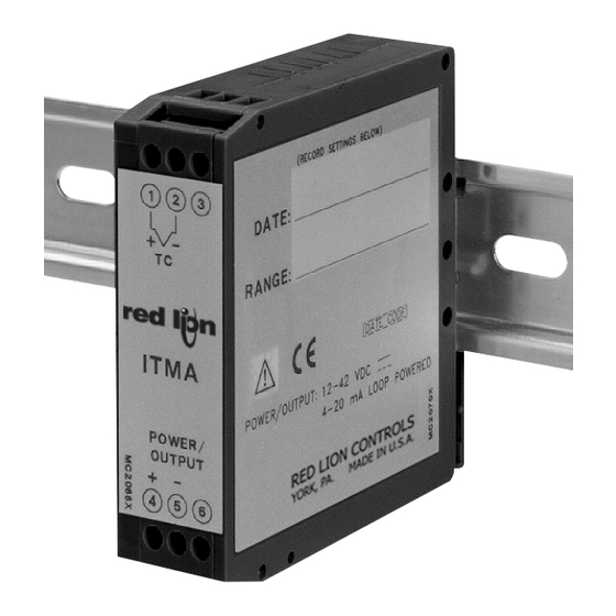
MODEL ITMA - INTELLIGENT THERMOCOUPLE MODULE WITH ANALOG OUTPUT
DESCRIPTION
The ITMA accepts a thermocouple or millivolt input and converts it into a 4
to 20 mA current output. The 4 to 20 mA output is linearly proportional to the
temperature or the millivolt input. This output is ideal for interfacing to
indicators, chart recorders, controllers, or other instrumentation equipment.
The ITMA is loop-powered which means that the same two wires are
carrying both the power and the output signal. The unit controls the output
current draw from 4 to 20 mA in direct proportion to the input change while
consuming less than 4 mA for power. The conversion to a current output signal
makes the ITMA less susceptible to noise interference and allows accurate
transmission over long distances. The 2-Way isolation allows the use of
grounded thermocouples which can provide additional noise reduction benefits.
The ITMA uses a ten position DIP switch to accomplish the input sensor
configuration, range selection, and unit calibration. A simple range setting
technique (Field Calibration) is used so the actual input signal adjusts the output
current for scaling. This technique eliminates the need for potentiometers which
are vulnerable to changes due to vibration.
The unit is equipped with a universal mounting foot for attachment to
standard DIN style mounting rails, including top hat rail (T) according to EN 50
×
×
022 - 35
7.5 and 35
15, and G profile according to EN 50 035 - G 32.
SAFETY SUMMARY
All safety related regulations, local codes and instructions that appear in the
manual or on equipment must be observed to ensure personal safety and to
prevent damage to either the instrument or equipment connected to it. If
equipment is used in a manner not specified by the manufacturer, the protection
provided by the equipment may be impaired.
DIMENSIONS In inches (mm)
3.11 (79.0)
ORDERING INFORMATION
MODEL NO.
DESCRIPTION
ITMA
Intelligent Thermocouple Module
.886
(22.5)
1
2
-
+
TC
3.30
ITMA
(83.8)
POWER/
OUTPUT
4
5
PART NUMBER
ITMA2003
z USER PROGRAMMABLE INPUT
(THERMOCOUPLE TYPES J, K, T, & E, OR MILLIVOLT)
z 12 TO 42 VDC LOOP POWERED (4 TO 20 MA OUTPUT)
z MICROPROCESSOR CONTROLLED
z SIMPLE ADJUSTABLE RANGE SETTING (USING INPUT SIGNAL)
z THERMOCOUPLE BREAK DETECTION
z MOUNTS ON "T" AND "G" STYLE DIN RAILS
z 2-WAY ELECTRICAL ISOLATION (INPUT/OUTPUT & POWER)
z HIGH-DENSITY PACKAGING (22.5 MM WIDE)
z WIDE OPERATING TEMPERATURE RANGE
CAUTION: Read complete Instructions prior
to installation and operation of the unit.
SPECIFICATIONS
1. POWER: 12 to 42 VDC *(Loop powered). The power supply must have a
30 mA min. capacity.
[* Min. voltage must be increased to include the drop across any current
display indicator]
2. INPUT: J, K, T, E, mV [selectable via DIP switch]
3. OUTPUT: Loop powered (passive), 4 to 20 mA Linear output
Ripple: Less than 15 mV peak-to-peak max., across 250
to 120 Hz frequencies).
4. RANGE & ACCURACY: (12 Bit resolution)
Accuracy: ± ( 0.075% Range + 0.25°C [Conformity] + 0.50°C [Ice Point])
at 23°C after 20 min. warm-up, conforming to ITS-90.
Note: TC Conformity and Ice Point do not apply to mV input.
Relative Humidity: Less than 85% RH (non-condensing)
Span: The input span can be set to a min. of 1/8 of the full scale range,
anywhere within that range.
Thermocouple Accuracy for each type and the corresponding ranges:
DIP SWITCH
TC
RANGE
TYPE RANGE
(INPUT)
6 7 8 9 10
0
0 0 0 0 0 -136 to 111°C
1
0 0 0 0 1
J
2
0 0 0 1 0
3
0 0 0 1 1 -149 to 862°C
0
0 0 1 0 0 -200 to 541°C
1
0 0 1 0 1 427 to 1132°C
K
2
0 0 1 1 0 648 to 1372°C
3
0 0 1 1 1 -192 to 1372°C
0
0 1 0 0 0 -225 to 149°C
3
1
0 1 0 0 1
T
2
0 1 0 1 0
3
0 1 0 1 1 -200 to 400°C
0
0 1 1 0 0 -111 to 311°C
1
0 1 1 0 1 276 to 609°C
E
2
0 1 1 1 0
3
0 1 1 1 1
6
0
1 1 1 0 0
1
1 1 1 0 1
mV
2
1 1 1 1 0
3
1 1 1 1 1
Note: DIP switch settings
Accuracy Example:
Type "J" Range "0"
-136°C to 111°C
1
Bulletin No. ITMA-E
Drawing No. LP0382
Released 04/13
TEMPERATURE
RANGE
& mV RANGE
ACCURACY
± 0.19°C
69 to 575°C
± 0.38°C
White (+)
338 to 800°C
± 0.35°C
± 0.76°C
± 0.56°C
± 0.53°C
Yellow (+)
± 0.54°C
± 1.17°C
± 0.28°C
74 to 326°C
± 0.19°C
68 to 400°C
± 0.25°C
± 0.45°C
± 0.32°C
± 0.25°C
377 to 1000°C
± 0.47°C
-114 to 1000°C
± 0.84°C
-9 to 6 mV
± 0.0113 mV
-9 to 22 mV
± 0.0233 mV
-9 to 63 mV
± 0.0540 mV
-9 to 77 mV
± 0.0645 mV
ON = 1
OFF = 0
Range
Conformity
Ice Point
( ±0.19°C +
±0.25°C
+ ±0.50°C ) =
Ω
load resistor (up
WIRE COLOR
ANSI
BS1843
Yellow (+)
Red (-)
Blue (-)
Brown (+)
Red (-)
Blue (-)
Blue (+)
White (+)
Red (-)
Blue (-)
Violet (+)
Brown (+)
Red (-)
Blue (-)
N/A
N/A
Total Error
±0.94°C
Advertisement
Table of Contents

Related Manuals for red lion ITMA


Summary of Contents for red lion ITMA
- Page 1 DESCRIPTION CAUTION: Read complete Instructions prior The ITMA accepts a thermocouple or millivolt input and converts it into a 4 to installation and operation of the unit. to 20 mA current output. The 4 to 20 mA output is linearly proportional to the temperature or the millivolt input.
-
Page 2: Factory Settings
The unit is shipped from the factory calibrated for a 4 to 20 mA output using 6. RESPONSE TIME: 400 msec (to within 99% of final value w/step input; a type J thermocouple in range 3. The ITMA should be Field calibrated by the typically, response is limited to response time of probe.) operator for the application environment it will be used in. - Page 3 Line Filters for input power cables: probe cannot be connected directly to the module, thermocouple wire or Schaffner # FN2010-1/07 (Red Lion Controls # LFIL0000) thermocouple extension-grade wire must be used to extend the connection points 6. To protect relay contacts that control inductive loads and to minimize radiated (copper wire does not work).
-
Page 4: Calibration Procedures
TC TYPE 2.14 Set the ICE PT EN/DIS switch (#4) OFF to enable Ice Point Compensation. TC TYPE RANGE 2.15 Disconnect millivolt source from the ITMA and connect the actual sensor to be used RANGE Step 2.13 in the application. - Page 5 1 2 3 4 5 6 7 Ice Point Calibration Wiring Step 3.5 3.5 Set the OUTPUT CAL switch (#1) ON and then OFF. 1 2 3 4 5 6 7 RED LION CONTROLS YORK, PA. MADE IN U.S.A. Test MODEL ITMA Step 3.5...
- Page 6 Steps 4.3 to 4.15 4.11 Set the OUTPUT CAL switch (#1) ON and then OFF. 4.12 Input 63 mV and wait 5 seconds. RED LION CONTROLS 4.13 Set the OUTPUT CAL switch (#1) ON and then OFF. YORK, PA. MADE IN U.S.A.
-
Page 7: Installation
A meat processing plant needs to keep daily records of the process area temperature. FDA regulations require the temperature to be 22°C at all times. The ITMA can be used for this application, with the added benefit of being DIN rail mounted to save space. -
Page 8: Limited Warranty
The Company disclaims all liability for any affirmation, promise or representation with respect to the products. The customer agrees to hold Red Lion Controls harmless from, defend, and indemnify RLC against damages, claims, and expenses arising out of subsequent sales of RLC products or products...
Need help?
Do you have a question about the ITMA and is the answer not in the manual?
Questions and answers